But RuiDa controllers were using the same designed LPS units on K50s doing computer controlled LPS-IN laser power control.
I’ve read through both of Don’s writings on the LPS and it has not popped out at me that there is any comparison of computer controlled LPS-IN along with LPS-L being better or worst than purely LPS-L control.
Did Don’s writings precede the creation of open source firmware controlling the LPS and that is why they all use a single control signal while RuiDa continues to use 2 control signals?
Jack is sold on RuiDa being so much better than other controllers and I’ve had others tell me I should put a RuiDa in my laser because it’s better and works great… Just trying to figure out if there is anything too this and I will read over both of Don’s articles again and see if anything sinks in but I did not see anything which stood out about the RuiDa methodology of dual control signal lasering.
This is how the Ruida controller is controlling the power supply by simultaneously controlling L and IN and therefore the output. Of course it is using a signal/voltage and not a pot for the IN.
The simpler replacement controllers can only control one input at a time.
Yes! Laserweb was one of the earliest alternative softwares available but does predate Don’s involvement. As I stated above they started controlling the IN input until they realized you could PWM the L input.
@jkwilborn They are tasty only ate one once due to an ugly tangle of hooks that killed it.
I release these beauties so they go get bigger!
@jkwilbornto computer control or not is irrelevant. Any of this stuff can be computer controlled.
The difference in these approaches is whether there is a way to adjust laser power outside of a programmed job. That could be a pot or a PWM from a computer.
How do you know that Trocen uses the same method as Ruida? I never found any wiring, nor controller schematics. That info would be interesting.
@dougl check out my updated paragraph above on why I suspect [but am guessing] Ruida may have chosen their approach. I think that the separate control of L is so they can enable/disable the LPS from the controller’s control panel and we are trying to make it something more than that.
Editorial
I don’t think that the power control technique is what makes the Ruida controller better. I looked at it long and hard. I did not use it because it was not open source. The Nano convinced me never to design a closed controller into any of my tools and I haven’t.
I think Ruida’s user interface is superior to all the configuration of controllers that I have seen and if you do not want or can’t configure a controller like a smoothie then the Ruida is a very attractive plug-and-play choice.
If this is an important question to answer then the right way to answer this question is to stack rank key features into a matrix. Then score the controller candidates against those features finally adding up the scores.
Except the RuiDa is dynamically varying the LPS-IN signal and is NOT doing what the other controllers do which purely uses the POT on LPS-IN as a maximum output power setting. I looked on a scope and LPS-IN is dynamically changing within the same layer and not a fixed setting per layer.
Once again this is a either or setup and I get that it is how all the other firmware does laser control.
Or are you saying that previously the open source firmware would control both laser enable(LPS-L) and power control(LPS-IN) then later switched to only LPS-L?
I cannot have an opinion about your apparent discovery of dynamic control of both IN and L as I have not seen the scope traces you mention. Did I miss them?
All of the scope traces I have seen have not proven to me that they are synced in such a fashion as to know what part of the imaging process they are showing. As you likely realize it’s easy to be fooled by out-of-sync scope traces.
I do not know how you could isolate these signals to a layer unless you used a storage scope over a long period but you still need a known sync point. That or some kind of clever sync point.
This is not to say you haven’t it’s just that I have not been convinced.
I think if @dougl is looking for something that is logical…
As Don noted the pwm/analog goes into the IN connection. This is what sets the internal pwm cycle to switch the state in the tube on or off.
The L, H or P inputs could probably all serve the same purpose. If I remember correct they all enable/disable the internal pwm…? The L input ‘enables’ the pwm generation, as I thought does the P (water protect) input… H is just an inverted L input.
Since the lps is designed to have it’s pwm controlled by the IN input analog or digital.
In my mind I’d control/connect it to the IN input as designed/suggested by the manufacturer.
Are there K40 controllers out there that have a ‘laser enable’ of some type and use the pwm as the IN of the lps?
I don’t recall the schematic and can only find the hv part, sorry Don… some of the links are dead in your document on the last visit.
I’m not sure here. I have these wired up and syncing off the L-On, everything is relative to the trigger.?
Can’t have that
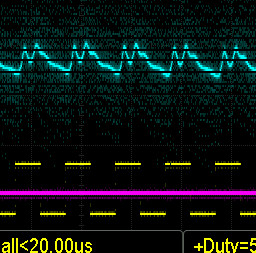
In all but one, I am just ‘drawing’ a straight line. You can see the pwm duty cycle at the bottom.
Here is a short explanation of the screenshots.
The blue is voltage across the mA meter. If I remember correctly the line ran at about 24kV.
Purple is the L-On → IN on the lps, which is also the trigger.
Yellow is the pwm at 50%. Pwm has a 1mS period (1kHz).
Pwm on the Ruida is usually set to 50uS (20kHz). Normally the pwm would be 20 times faster.
However it does bring up the question about lps response times.
Most lps that I’ve seen the specifications state that it will produce 90% of the placarded voltage in <=1mS.
So I can ‘toggle’ it 1000 times in 1 second or 1s/1000. If my pwm is set to 20kHz, it’s operating 20 times faster than that. So what determines response time.?
What input gives the quickest response time, the L or IN input?
What if you send it a signal that’s faster than it can respond … what’s the result…?
I think this is simply a belief held by people who are used to stuff like that being expensive because it is being sold in small quantities to companies who don’t care a lot about price. As you say, once stuff like controllers start being mass-produced, economy of scale kicks in and the price drops massively. Expired patents can also increase competition and drive prices further down.
I haven’t seen these commercially based controllers go down in price.
I can get a 50 watt tube at a lower cost than a Ruida 6442. Component wise, that would make the Ruida the single most expensive component in my machine …
RuiDa is now licensing their design to other companies or maybe even shipping product to them with rebranding going on. The firmware compatibility remains from what I’ve heard so what this does is allow them to both keep their own brand at a high markup and keep their protocol and hooks/ties with the software side.
On the CNC side it also took years but Mesa has greatly dropped their prices so it’s no longer ~$400 just to get an interface between a PC to a CNC machine. I think it’s closer to half that now via Mesa boards.
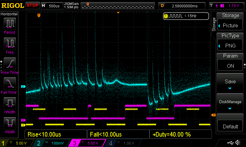
I am going to do a video of the RuiDa on the bench running the default design showing the L-ON1, LPWM1 and LAN1 outputs during a portion of running the doily design.
Generally:
L-ON1 is wired to LPS-L
LPWM1 is wired to LPS-IN
What you see in the video: When L-ON1 is low(bottom trace) the laser output is on/enabled and while L-ON1 is low you can see the PC(Power Control) LPWM1 is showing it is varying the laser power. ie PC is changing while laser is Enabled. Most likely this is happening in this design because of the set speed and the fact the machine can hold 200 mm/s for all the turns and moves so as it must decrease speed it also decreases output power. Likewise, as speed is increasing it will increase the output power.
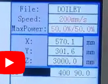
IMHO, It’s missing what the complete speed and min/max power settings. It’s missing the value of the minimum power setting, if any.
I recall him saying that when it’s low the pwm is still running. Sounds like he’s thinking L-On is active high. I posted a correction, if that was the case and left it at that.
He’s not clear or doesn’t know how to read the console on the Ruida.
The upper part of the display shows what’s set in the controller manually, by using the min/max and speed buttons on the console…
It only overrides the layer settings when you manually change it during a run.
Unless he has manipulated them, during the run, the display of the layer is 400mm/s @ 90% and that’s what it will attempt to run.
The pwm in the video doesn’t look like either 50% or 90%. Since we don’t know what the minimum power is set we can’t make much of a judgement about the viewed pwm except…
He can’t have the 50%/50% (minimum = maximum) power setting and have the pwm change when it executes… That’s not how I understand the Ruida and have made used of it.
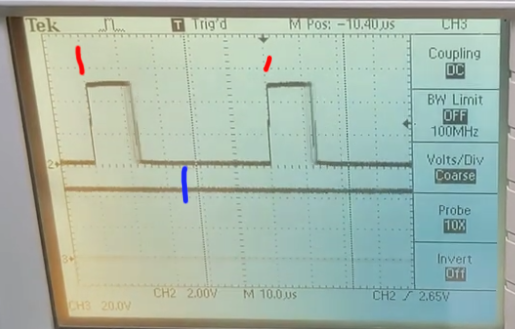
It is running the stock period of 50uS (20kHz), as you can see on the scope. The pwm never makes the 50% level. That would be between the two rising edges of the trigger, which appears to be the pwm signal.
Between the red marks is the pwm period of 50uS, 10uS/division. The blue mark is approximately half way (25uS) which would be 50% pwm if the falling edge makes it to that point.
So I’m not sure what he’s up to… or trying to show.
Jack, there are 2 schools on how to run the typical LPS. Somewhere in the crud up above this post this was mentioned more than once but got lost.
School 1( I only name this #1 because it’s what I want to mention first ).
Fix LPS-IN at a single voltage( or PWM ) which represents the maximum power measured through the milli-ampere meter.
Send a squarewave( active Low ) through LPS-L which does both ON/OFF of the laser for the design and manipulates how much power is put into each pixel by turning off the laser part way through the pixel timing.
School 2( RuiDa )
dynamically vary the laser power using PWM into LPS-IN signal
Send a squarewave(active Low ) through LPS-L which only controls when to turn the laser ON/OFF for a segment or pixel.
Having shown on the scope that the RuiDa controller does dynamically vary the PWM signal while the laser is enabled(low on LPS-L) it would make sense that the LPS-L(RuiDA-L-ON1) is active(low) for the entire pixel duration since power is adjusted via PWM(RuiDA-LPWM1).
Not really … you are adjusting the max ‘on’ period pwm to limit average current. Call if what you want, it’s still the pwm controlling the lps, digital or analog. Pwm is running continuously.
What I’ve been trying to say is it’s doing the same thing in both cases.
If you set the pwm to 80% pwm for max average current you want via a pot. Then you toggle the L of the lps control with a 50% pwm, you will get 50% of your 80% pwm or 50% of the max average current.
In effect you are pwming a pwm signal for control.
Except one being dynamic there is no difference between your two schools of thought… and if it changed to a grayscale, it will also be a dynamic pwm change, grbl or Ruida.
Didn’t think this was ever in question, but how else could it control the power?
Don’t know what he was trying to show with the Ruida video… do you? It was kind of moot something.
So @jkwilborn , you are saying that the output lasing methodology, what ends up burning wood, is exactly the same no matter if you are running the LPS with a dual control Ruida setup OR a single Smoothieware control setup?
I just really have a VERY hard time following you with what is pwm and what is not… I tried using LPS labels so that I could talk about 2 different connectivity setups and you consistently talk/use Ruida labels. I really can not follow what and where are these pwm signals and I think you are talking about an internal high frequency PWM which drives the laser output circuit or is LPS-L now being called a pwm signal?
I tried to follow Don’s explanations but he likes to refer to the component pins of the schematic and I don’t have that schematic or functional model visualized so it just didn’t sink in what was being modulated and how they tied to the final laser output control.
But hey, if there is no difference between controlling the LPS the way RuiDa does it(with 2 lines) and the way GRBL/Smoothieware/RepRapFW/Marlin/etc do it then my efforts to look at what/how RuiDa is doing it was a waste of time and the comparison probably comes down to what UI is better, the RuiDa on the machine or all the settings in the open source firmware and spit out into GCode.
I’m very sorry, the hopes are not to confuse you and I did refer to L-On instead of L. I did fix that.
Whatever controller you use, the lps is a different component and requires 2 signals for it to operate, L and IN. No matter what you use to control it, the lps is a two signal control system.
The IN input is ALWAYS the pwm or power control for the lps. Doesn’t matter if you use a ‘pot’ or the pwm output from the Ruida.
L is always the laser enable. When it is asserted, it will lase at the IN pwm frequency, just like what happens with the Ruida.
You set IN with a pot, to say, 80%, assuming that’s the maximum average current you want. If you pull L low, it will lase at 80%, just like you set it with the pot… not unexpected.
If you now apply any pwm signal to the L input, the laser will lase the whole time the L input is low at 80% power as set by the pot or analog voltage on IN.
If I turn it on for 50% of the time, I get 50% of the 80% power…