Sorry for the delay it’s that time of year and I was out fishing:
Frankly, I am unclear as to the purpose behind this “why RuiDa” thread.
I will do my best to answer the questions.
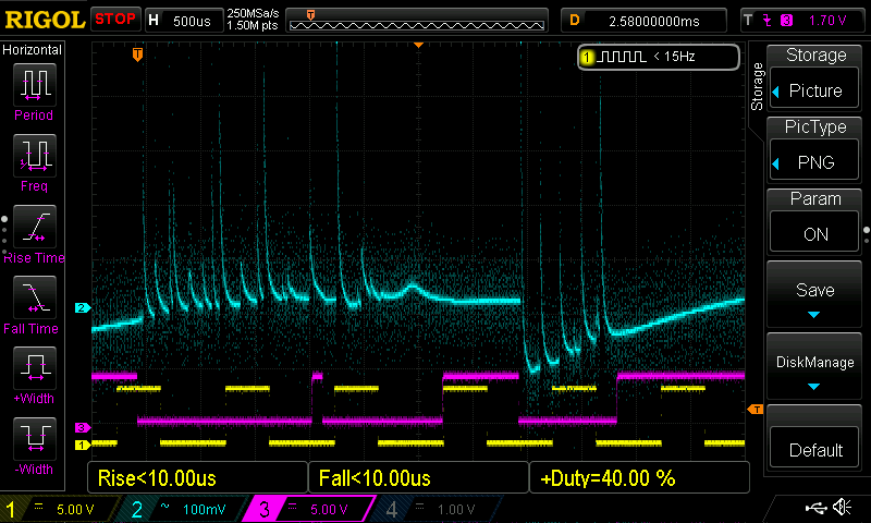
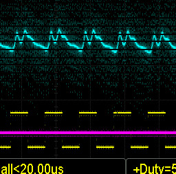
Scoping a CO2 laser system:
Depending on what you are trying to measure the scope traces won’t be very meaningful unless a means of syncing it with the programmed movement is employed. In addition, imaging a resolution pattern why scoping would help us understand the electronic response of the system.
I started down this “scoping” road some time ago with the intent of measuring the CO2 gas laser response time. Gass lasers were not typically used in a switched mode. Rather the optical output was switched using various optical interrupting devices.
Then someone helped Russ scope out the anode side of the LPS, which satiated me. That test is on Rus’s YouTube channel. It showed that my suspicion that the laser was not fast enough was wrong.
I did come out of the work with a better PWM DF than many use today.
To date, there are still unanswered questions as to the exact laser firing characteristics. Turns out it matters less than measuring the response at the surface and that’s safer  ! So I moved on
If we want to know the response of the system:
I have suggested many times that testing the response of this system is best done by looking at the “built-in scope”, i.e the image. This can be done by imaging an increasing pattern with increasingly wider lines and spaces. If you want to try this out program a pattern and send it to the inkjet or laser printer.
Not sure I understand this question but let’s try an explanation that follows my logic in the context of this thread.
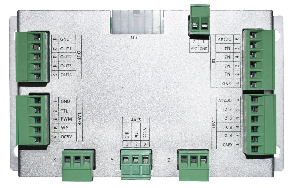
How the LPS is controlled:
L: this ground true signal enables/disables the supply by controlling the internal PWM control. This pin is connected to the cathode of an Opto coupler so it is not a TTL signal rather it needs solid ground to turn on the supply. In fact, even a small shift from the supply ground potential will disable or cause erratic operation of the supply.
In some supply configurations, the L is also connected to another L pin which is connected to the Laser Test switch on the control panel.
IN: this signal is an analog input that is connected through a 1Khz filter which is connected to the PWM control of the supply. The PWM of the supply is controlled with a 0-5VDC signal whereas 5VDC is 100% DF. This signal has no optical isolation. The supply’s internal PWM controller directly drives the H switch which goes on to create the HV.
I will not elaborate on the other controls because they essentially disable the supply when interlocks and/or the cooling circuit is open.
The original K40 design:
If the machine only “dithered” then the LPS only needed to turn full on/off. The L signal was all that was needed.
Evidentially it was understood that a manual intensity control of laser power was needed.
I did not understand the need for this until I started using my machine.
The IN function provided an intensity control. A pot is a pretty cheap means of analog control and it was placed on the control panel. Its only downside was that it was not very accurate. This is why I added a DVM to the pot’s wiper.
Were not in Kansas anymore [L+IN};
We needed to control the LPS from a G-Code capable controller that could provide greyscale engraving, vector, and yes dithered imaging. Power control had to be provided by a parameter in the controller’s g-code.
The controller I worked with was the smoothie which could provide a PWM output and enable function in one signal. The signal was OFF when no imaging was to take place and ON (some PWM value) when imaging was active.
The initial method of interfacing to the supply was by connecting a TTL signal through a level shifter to the IN port. In fact, I originally used this method but is IMO is a poor design that had many problems.
Then out of frustration caused by not knowing the internals of the LPS I (and others @Paul_de_Groot) started to dissect the LPS.
That is when it became apparent how the L could be used as the programmable port [with a simple open drain] and the IN used as the “intensity” control using the existing pot. In fact, this was much easier to implement as level shifting was unnecessary.
Separation of programed power and empircal adjustments:
After working with the L+ IN configuration and programming in LaserWeb the need for manual control became apparent to me. " I did not like constantly having to go into the program and change the power setting every time I changed materials. I wanted the programmed level of power to be in addition to the empirical (intensity) level of power.
Two empirical settings were needed that were best kept separate from the programmed job:
- The effect of the imaging substrate. A specific power level will image differently on different materials with varying moisture and other embedded content (glue).
- The effect of the tube’s changing power vs IN voltage characteristic curve (as the tube is used and/or ages).
A More direct answer:
What I don’t get in @donkjr documentation of his LPS analysis is why he only considered a LPS-IN control with both a PWM signal and a POT.
I did consider other approaches. Based on my actual use of the machine I wanted to retain a manual power control. I still think that is the best approach. But if the user is ok with constant tweaking on the program side, any configuration of PWM"ing IN and L will work. Just be prepared to change all your stored programs when you change the tube, or image on substrates with varying characteristics.
Editorial: I doubt the manufacturers of these machines and controllers care how much the user has to tweak to get good image quality. If they did these machines’ optics and motion control would be better designed.
To some degree, my choice was influenced by the available software and controller. The smoothie and its firmware were a perfect fit as the L signal being the only form of control, it was a composite of enabling and PWM. I also still think this is the best and simplest approach.
Alternate configurations:
Controlling the power (IN) separately from the enable (L) is technically sound. Its what controls the IN
WHOOPS HAVE TO STEP OUT …
… and he’s back!
Continuing on …
Configurations that do not provide an overriding intensity function:
- A. IN[G-code PWM power control], L[enable only]: whereas IN is derived directly from the G-code
Configurations that provide an overriding intensity function
- B. IN[Analog power control], L[PWM Gcode power control]: whereas IN is derived from an analog POT voltage, and power control is Gcode driven from L.
- C. IN [PWM power control], L[PWM Gcode power control ]: whereas IN is derived from an external PWM signal and power control is Gcode driven from L. . The digital panel works this way.
If any of the soft/firmware provided a user interface that could modify the programmed power by an intensity offset that added to the stored job that approach might be sufficient and make the entire practical control of the LPS “computer” controlled. If I was to implement such it would probably be configuration A.
The bottom line is that I chose B because:
- I wanted a way to override the total power outside the Gcode.
- IN and L are not TTL inputs. The digital engineer in me wanted IN to be analog and L to be an open drain. I expected this configuration to be less prone to ground shifts and noise.
- It was simple to implement with a smoothie. Many K40 users did not have the skill for anything more complex.
Why did Ruida use A:
Who really knows but my suspicions are:
- They do not know or understand the internals of the LPS and its control. I did not for a long time.
- They do not care (as many designs I have seen don’t) if their TTL outputs work in worse case interface conditions, including noise immunity … as long as they work … sort of.
- They did not understand or value the need for an intensity control
- They wanted to enable/disable the laser from the control panels’ firmware. You can do this by turning the power to zero [PWM DF =0] or pulling L high. [not a good safety protocol**]. The K40 digital panel works this way.
- They copied the multiple Maker builds where the power control is on IN. These makers did so because:
- They did not realize the smoothies’ power control is a composite and a separate enable was unnecessary. They did not care if there was an intensity control.
- They wanted software control of the laser’s enable [which violates all safety protocols**].
** laser enable should be a mechanical switch.