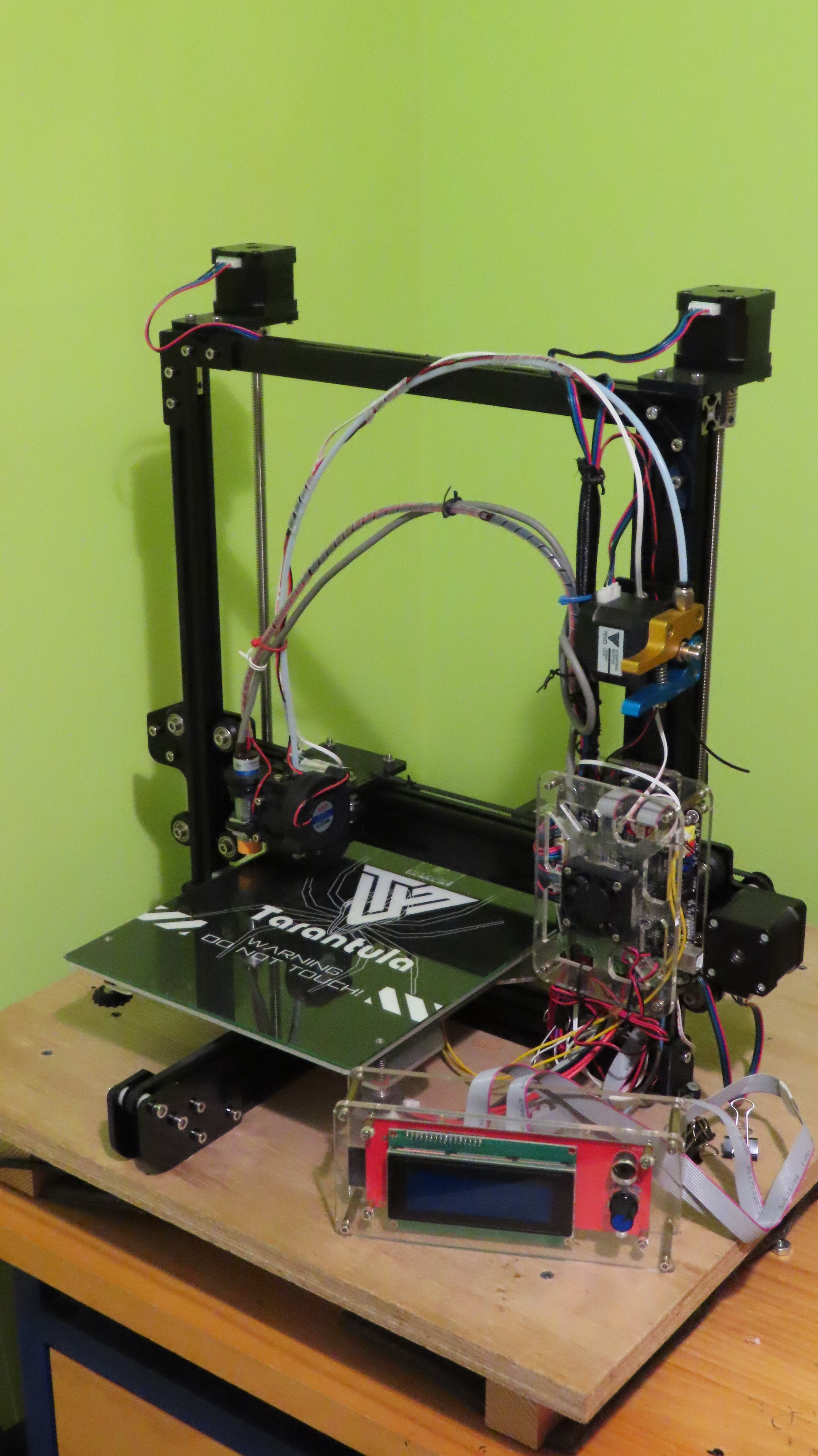
About five years ago, for my birthday, my family bought me a Tevo Tarantula. Not a 3D printer as much as a box with all of the components that when put together in the right way can produce 3D prints from GCODE. I had a LOT of fun putting it together, and upgrading it, by adding a second Z axis lead screw and motor, automatic levelling using a capacitive proximity sensor, etc etc. and I produced a large number of 3D prints for friends family and my workshop. In spite of the cool name, the Tarantula looks like a bit of a Frankenstein Monster, and I feel that the capacitive proximity sensor was a mistake in that the triggering distance is temperature sensitive and so the Z offset varies from print to print.
I retired a few months ago and upgrading the Tarantula (tidy up the cables, timing gear bearings, change levelling system to BLTouch, easy peel build plate) was put on the To Do list.
However a couple of weeks ago, a local hobbyist/electronics store put the Creality Ender 3 V2 Neo on special ($290 AUD). I could not pass it up… virtually no assembly, BL Touch, magnetic build plate, neat control interface - whisper quiet operation, cables neat and tidy… All of the upgrades that I wanted to make to the Tarantula already fitted and probably for about the same amount of money that I would have to spend on the Tarantula to upgrade it. This is considered to be an “entry level machine” but I don’t think that I need more…
Which brings me to the discussion part of the topic: What do folk think about dual Z lead screws? The The Ender 3 V2 Neo has only 1 but a second is available from Creality for $50 AUD.
My single-screw cantilever printer had layer height issues.
I don’t like having dual screws on dual motors. As @RaSTuS says, they can get out of sync. If you wire them in series instead of parallel this happens less. But the 4-start, 8mm lead screws still back-drive and get out of sync.
My solution on my Tronxy with dual screws was to put 2GT pulleys on the two lead screws, which I swapped out for single-start 2mm lead screws that don’t back-drive, and then used a loop of 2GT belt across a single motor to drive the two screws. I got the bed level once, and it’s never gotten out of sync since.
Credit to @Mark_Rehorst for pointing out that driving all the Z from a single motor keeps the axes in sync and completely gets rid of the sync problem.
Hi Michael ( @mcdanlj ), the upgrade from Creality comes with a single cable which splits the signal from a single Z port on the main board to the twwo stepper motors - Is this what you mean by connecting them in series? Dual Screws on 2GT pulleys and a single motor seems like a big and expensive job to me.
One concern over the Ender compared to the Tarantula: I can push the X gantry up and down with my hands on the Ender but not the Tarantula. As a result GCODEs written for Enders tend not to disable Z axis stepper at any stage, not even when parking the nozzle after a print.
@RaSTuS, @mcdanlj - How far out of sync do the screws get during a single print run? maybe its a simple matter to check that the x- gantry is level every once in a while.
@HalfNormal - I just watched a couple of “Before and After” YouTube videos… a right angled bracket was being printed to 88-89 degrees on a single Z Ender. Not a problem for decorative parts, but a major issue if the parts are technical. @mcdanlj will testify that I am very picky about my technical 3D printed parts…
@mcdanlj - I just visited another website and the pulley based single motor dual Z kit is available for $67 AUD - It comes with 2 screws and two brackets 2 timing gears and a timing belt tensioner. If I was prepared to pay $50 then I am prepared to spend $67, I guess.
It depends on the details of the single cable. It can be done either way.
If you split them in parallel, each stepper gets only half the current. If you split them in series, each stepper gets half the voltage but the whole configured current. For Z, at least with a 24V power supply as most new printers seem to use, that’s completely fine.
They don’t normally get out of sync while running, they typically get out of sync between runs.
Yeah, I haven’t priced all those parts separately, but that is basically what I would do with mostly the random parts I’ve already bought.
So if you have a problem that you are solving, I’d go for the single motor with belt solution over the dual motor solution, because it is more robust and less fidly.
Belt is also nice when moving to single start screws as I chose to do: it won’t back drive but you can grab the belt and move it in order to raise/lower Z manually.
Well, I don’t want the x gantry to sag. You can compensate for the sag by levelling the build plate, but the Y Z plane will not be perpendicular to the X Y plane. Fine in most cases, but as you know I tend to print a lot of technical parts.
I guess I could pinch (steal) the matching dual Z (non-backing) lead screws from the Tarantula, buy timing gears and belt, and print up dual Z X Gantry brackets for the Ender. Save myself $70 as the gears and timing belt will not be that expensive.
I would expect preload as the solution, not compensating with a trapezoidal system. At least, that’s what I did for my cantilever-supported gantry; I shimmed it square to the frame. I still had layer thickness consistency problems, so I gave up and bought a corexy printer instead of fixing up the bed-flinger.
Before adding dual Z I should check whether this is a problem with my shiny new Ender.
While only driven from one side, the gantry is supported on both sides by three V wheels - I may be able to adjust these ensuring that the X gantry is “preloaded” as you say ensuring that the Z is perpendicular to the build plate.
Might also be good to add a counterweight for the extruder and instead of centering every print, it may also be prudent to run some prints close to the side where the lead screw is. where the deviation is the least.
Probably one of them is on an eccentric cam. Too tight, though, and it will wear quickly.
This post from a few years ago has a link to a spreadsheet for calculating deflection for V-Slot of various sizes:
Here is that spreadsheet as a google sheet. You would want “Cantilever beam with a concentrated load” after putting an “x” for the v-slot profile in use, adding the mass of the head, and choosing the length at full extension.
You are probably looking at substantially less than 0.05mm deflection, which probably vanishes into variation in bed flatness.
Therefore, all that really matters is ensuring that the gantry is square to the Z tower and tram to the bed when it is static. If it isn’t already, you should be able to shim it. (Aluminum soda cans are sometimes useful for shim stock.) But I would expect that they considered this and that it’s already fine.
OK so now you’ve lost me more than a little. I think we may be over thinking this
I saw some YouTube videos where a difference between the heights at the two ends of the X- gantry was causing an upright vertical wall to be printed at 88 degrees with respect to the base. See from minute 27 of the following video:
This was corrected with the dual axis upgrade supplied buy the OM. That alone would make the upgrade worthwhile in my opinion.
Also, I don’t think that the cantilever bending calculations apply in this case. In a dual beam single Z screw system, the amount of sag at the side that’s not supported by the lead screw depends in the stiffness of the connection that the V wheels and the associated nuts and bolts can provide, and not the stiffness of the aluminium section as the Engineering Statics would imply. As you say there is a limit to how tight the V wheels can be made to track against the aluminium track.
The above posts didn’t give me a good sense of how big an issue the two Z motors getting out of synch is (how often what are the symptoms and how hard it is to fix it). My Tarantula has dual lead screws and I haven’t noticed much of a problem. In fact I don’t think that I have ever checked whether the two motors are “in Synch”.
Do you think that the single motor dual Z upgrade worth the bother or not? You seem to be in two minds about it…
To be honest I doubt that the OM have given this much thought… Certainly there seems to be enough people who like to tinker and enough of those that think that dual Z makes a real difference for a few companies to think that money can be made by offering the upgrade.
I’m saying to measure whether the X beam is actually out of square with the tower that supports it, on your printer, regardless of anyone else’s experiences shown in a video.
The 88° angle would be from the gantry being out of square to the tower it runs on. It seems unlikely that the tower would be out of square to the frame. I mentioned deflection only because I thought you were bringing it up, and I was suggesting that I didn’t think it would actually matter in practice.
If it is out of square, I would expect that shimming it might well be enough in practice.
If it is not enough, then I would use a single motor with belts to drive dual screws.
One thing I have done with one printer is to replace the extrusion stepper with a lighter one. This puts less weight on the Z axis. This was more of an experiment when I was having extrusion issues and not because of actual issues when printing. The smaller stepper works fine for standard filament so far.
You have always provided good advice and I am very grateful to receive it. What’s more I agree with the overall conclusion, which is along the lines of: “Don’t go spending too much money and effort trying to solve a problem that does not exist, and when it does exist then simple cheap solutions are usually sufficient and therefore elegant”…
The filament feeding stepper (E) in my Tarantula is fixed and attached to the Z frame, not the hot end carriage. In the Ender 3 V2 Neo, the filament stepper is attached to the lead screw nut bracket - That is it moves up and down along the Z but not its fixed along the X and Y axis. Its mounted almost right on top of the lead screw, so it should not be putting any torsional force on the X Z plane.
It’s another reason why - @mcdanlj is probably right.

")