@Ben_Myers many thanks?
@donkjr Just thanking you for all your hard work you do for this community and helping me with an unsupported board. I really appreciate it.
1 Like
if I change the laser_module_pwm_period from 400 to 20 the machine cuts perfect again… but pwm is no good
@Ben_Myers I have never compared cutting on this config vs the Nano setup.
I am guessing but never proven empirically that the higher frequency PWM is providing a PPI kind of effect when cutting. This is a beneficial artifact of running the PWM period to fast for the lasers response time.
However lower period settings are two fast for the information that we are feeding the laser, at these speeds, during engraving. The data in vector cutting is typically slower.
So, lower PWM setting artificially enable cutting with lower power but that same setting is to fast for engraving.
This may be one of the trade-offs with this setup. I suggest cutting down the speed and doing both engraving and cutting comparisons.
Most users are finding an optimum place to run both.
…
What speed are you running in this comparison
Actually you are the first that has mentioned this, at least that I recall.
What is the difference in current vs cut vs thickness vs speed of the same material?
The variables that I am assuming you have not changed between the before and after cutting comparison are:
…Laser power including any alignment issues
…Surface speed (feed rates)
…Material type and thickness
… Theory trying to be practice …
Now that I am inside the LPS I recently measured its period to be closer to the the 400 us range which matches my theoretical calculations for the threshold for acceptable engraving.
I have for some time thought that the the single control schema and speeds that we are using marginally meet our expectations for marking quality and speeds. In fact that is what caused me to start the laser control and LPS research that seems to have become an obsession.
The theory and some of the empirical tests that I have done when mixed with some research information suggests that we are expecting the laser to switch to fast.
The stock K40 does not engrave rather it dithers so it does not have the same problem we are dealing with. Its internal LPS PWM is probably matched to the laser response and it is a constant setting from the pot.
In our design we are sending a PWM signal that controls both power levels and marking data in a single system. That signal is then again modulated by the LPS constant internal PWM. My models show that it is not possible to optimize the laser control with this single control.
Concepts that can be combined to optimize with a larger PWM period setting:
- Slow down the feed rates
- Dither instead of engrave
- Make PWM a variable control
- Design a dual power control schema
- Add PPI control
I have not had time to test the above concepts but I have started work on a design for #4.
@donkjr thank you for your detailed reply. I will try to answer all your questions
“What is the difference in current vs cut vs thickness vs speed of the same material?” - I will run these test and post back
------------------------------------------------------------------------------------------------
“The variables that I am assuming you have not changed between the before and after cutting comparison are:”
…Laser power including any alignment issues - Can swap back to M2 Nano board and it cuts fine
…Surface speed (feed rates) - Same as Nano
…Material type and thickness - Same as Nano
------------------------------------------------------------------------------------------------
Concepts that can be combined to optimize with a larger PWM period setting:
- Make PWM a variable control - Could we have 2 values in the config e.g.
- laser_module_pwm_cut_period - 20us
- laser_module_pwm_engrave_period - 400us
We would need to have Laserweb read these settings and apply them to the g-code generator or maybe as you stated just be able to type in each layer of laserweb the pwm period.
@donkjr I think I may have figured out why I am not getting decent cuts… (well you did) I cam across your post about cooling water
https://plus.google.com/+DonKleinschnitz/posts/jDRGVhd6zqy
and after changing to demineralised water (couldnt find Distilled)
it is cutting much better. I’m only a few cut in but thr results look much better. You are a genius.
@Ben_Myers I am glad the research has helped you and thanks for following up so that we can see cause and effect.
I think the genius is @HP_Persson as his tenacity in getting awareness of this problem drove us to investigate. Also @Nedman 's chemistry expertise was invaluable in wading through the mire of solutions.
You now join a growing group of believers that “Cooling Water Matters”…
@donkjr as an example with the Nano board I cut at 8mm/s @ 16ma. with the new water I now can cut at 8mm/s @ 7ma. Definitely better.
Still need a better solution to allow for different pwm setting for cut and engrave in laserweb/smoothieboard.
@donkjr did I read this correctly regarding the K40 LPS?
An optimal PWM base preriod/frequency for engraving is 400uS/2.5KHz
An optimal PWM base period/frequency for cutting is 20uS/50KHz
I currently had/have Smoothieware set to 200uS/5KHz
I’m figuring out the spindle setup of LinuxCNC and Remora and have things almost working except I noticed the base frequency of my setup is changing with the spindle speed setting( gcode Sxxxx ) so I’m looking into how to set it to a fixed frequency. And maybe, since LinuxCNC is so flexible in configuration I may be able to monitor head velocity and switch the base PWM frequency since cutting generally operates at lower speeds than engraving. Or I could add a new M code which triggers changing of the base frequency.
The research and modelling that I did is here [in case you didn’t see it].
I started this work because I had evidence on my machine that engraving on a K40 was unpredictable.
I theorized that there was a point at which the combination of K40 + controller machine parameters could result in a condition where the PWM ON signal would be two short for the laser to respond. One of those machine parameters was the PWM frequency but the practical effect on engraving depends on multiple factors.
The essence of the model was to find the cutoff point for machine parameters. Where @ the lowest grayscale value [10%] the pulse width of the ON part of the PWM signal would be shorter than the lasers response and therefore would not image.
The model suggested a reasonable starting point for the PWM frequency setting at a typical set of machine settings. The model further predicted that at stock settings for the K40 the default Smoothie setting were 10x too fast.
The model is based on a guess as to the lasers response time which we really do not know. The lasers actual response time is a convolution of electrical, optical and material response times all of which we are unsure of or at best vary substantially.
The single reference to the lasers ionization time I could find produced model results that said the K40 could not engrave reliably, yet it does engrave, sort of. That is if you tweak it.
Note: I suspect this is why the stock controller used dithering vs PWM control.
Users reported that in general they got better engraving at the 200us frequency so I suggested that as a starting point and moved on :).
The practical answer ended up being @ a certain PWM freq. setting if your engraving is poor slow the machine way down. The 200us point provided a better starting point than the stock 20us.
I did not include cutting in the PWM frequency analysis. Off the top of my head I do not see how cutting would be improved with a higher PWM frequency, that is, unless there is some kind of a PPI or ionization edge effect.
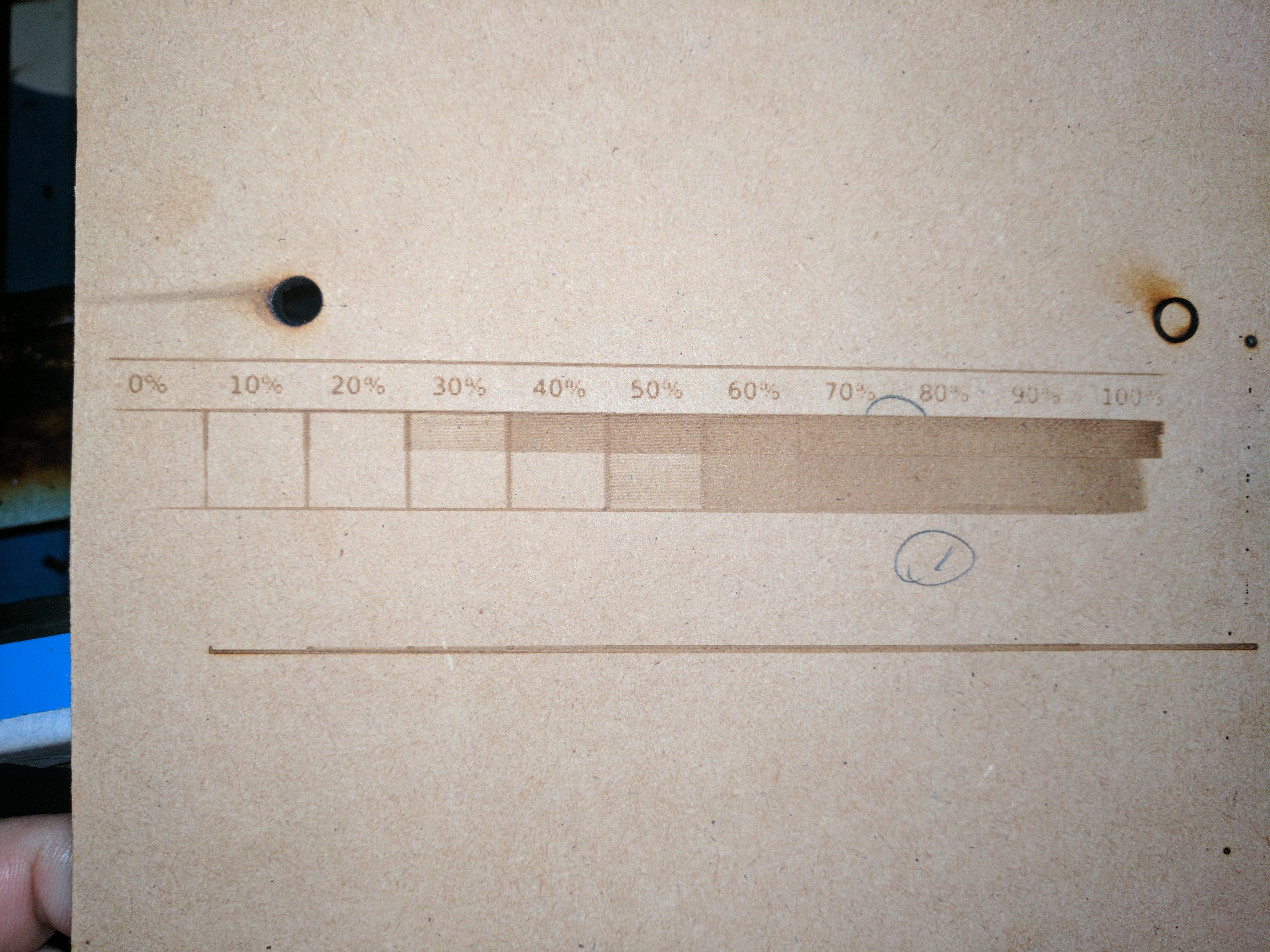
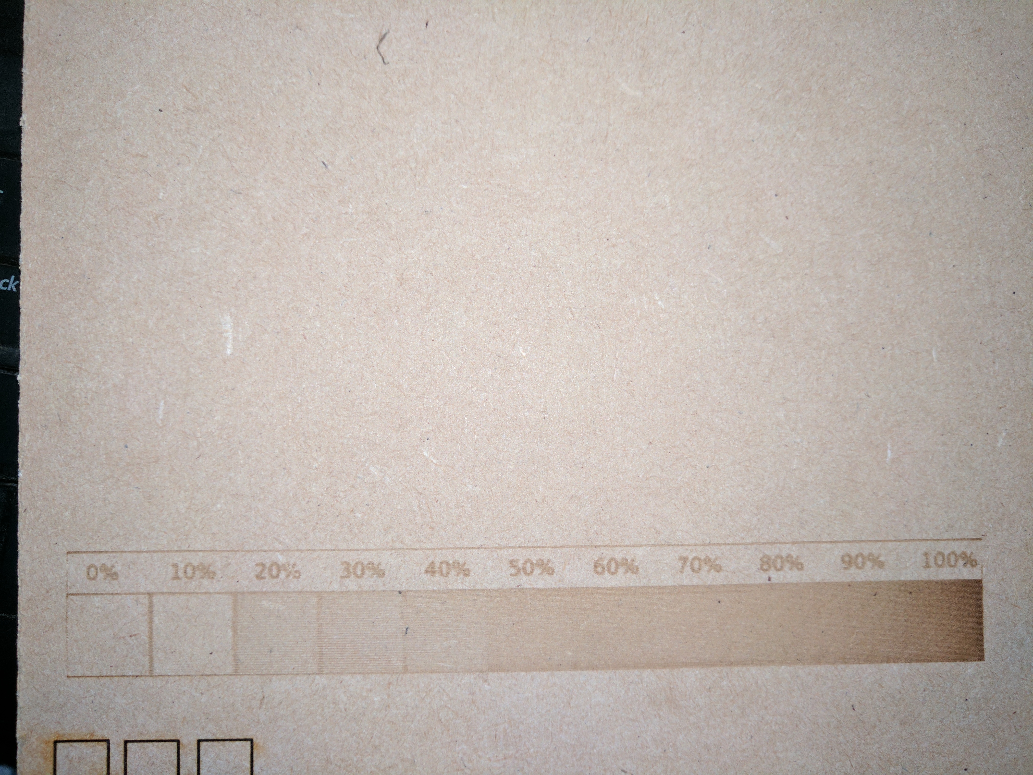
I concluded that the practical solution for determining the systems optical response was to create a frequency response test to use as gauge for understanding a specific machines overall response characteristics.
In a previous life, where I designed laser printers, we would print a pattern that would show us the frequency response of the entire marking system.
This entailed a horizontal and vertical set of lines that had various frequency of on-off cycles. The highest frequency of which was one dot on and one dot off. I did not complete this on my machine but I would bet that at the speed most run their K40 it could not image a one-dot on one-dot-off pattern that could be resolved. I am still anxious to find out but I have so many projects!
These marking patterns were varied to simulate conditions such as:
- one-dot-on one-dot-off
- two-dots-on two-dots-off
- three-dots-on three-dots-off
- …
- one-dot-on one-dot-off
- two-dots-on one-dot-off
- three-dots-on one-dot-off
- …
An example of this test is in this post:
I never finished designing that marking test because I suspected it would not be used. Most users just tweak their machine until they get satisfactory engraving… for every job… for every material.
5 Likes
Thanks Don, that was fantastic work and documentation!
2 Likes
A silly question, how does a 3rd party board produce the required -4V and GND trigger levels for L? When its only powered from 0V and 24V Does it need a special DC/DC converter?
Do you PWM this L line, or another?
There is no nagative voltage involved. The L pin only needs to be connected to GND to fire the laser.
Most boards use a MOSFET for this. The drain of the mosfet is connected to L and the source is connected to GND. When the MCU delivers a 5V (or 3.3V) signal to the mosfet gate, the mosfet switches on and L is pulled to GND.
3 Likes
Any idea why people keep thinking L control takes a negative voltage? I’ve seen this statement a few times now so something is pulling them in the wrong direction. Literally.
 I have been explaining how the L input works since way back when I released the first (and only) LPS schematic.
Seems it’s hard for K40 hackers to comprehend that a simple ground asserts the L signal. In fact, anything other than a hard ground can cause problems. Perhaps it sounds too simple to be true :). The continuingly poor advice on controlling IN vs L also makes this situation more confusing for electronics novices.
I know on the K40 FB forum, where most K40 users go for help, there is a gaggle of bad information. In fact, that is why I do not participate over there anymore.
4 Likes
I get when people have had no basic electronics and are just flying by the seat of their pants trying to figure stuff out but there seems to be something or somewhere telling them a “negative voltage” needs to be applied to the L signal. Maybe it’s a label like “-L” which is throwing them off since nowhere do I recall reading it being “active Low” triggered. If it were we’d be hearing questions about what “active low” means or how to make L go “active low”.
A google search would have explained that terminology in a way understandable to many - what does active low mean in electronics - Google Search
Hopefully people walk away having a little bit more of an understanding of electronics and the L signal sure seems like a beacon of confusion.
2 Likes
What is really fun is that the cathode ground on some supplies is labeled -L. 
3 Likes