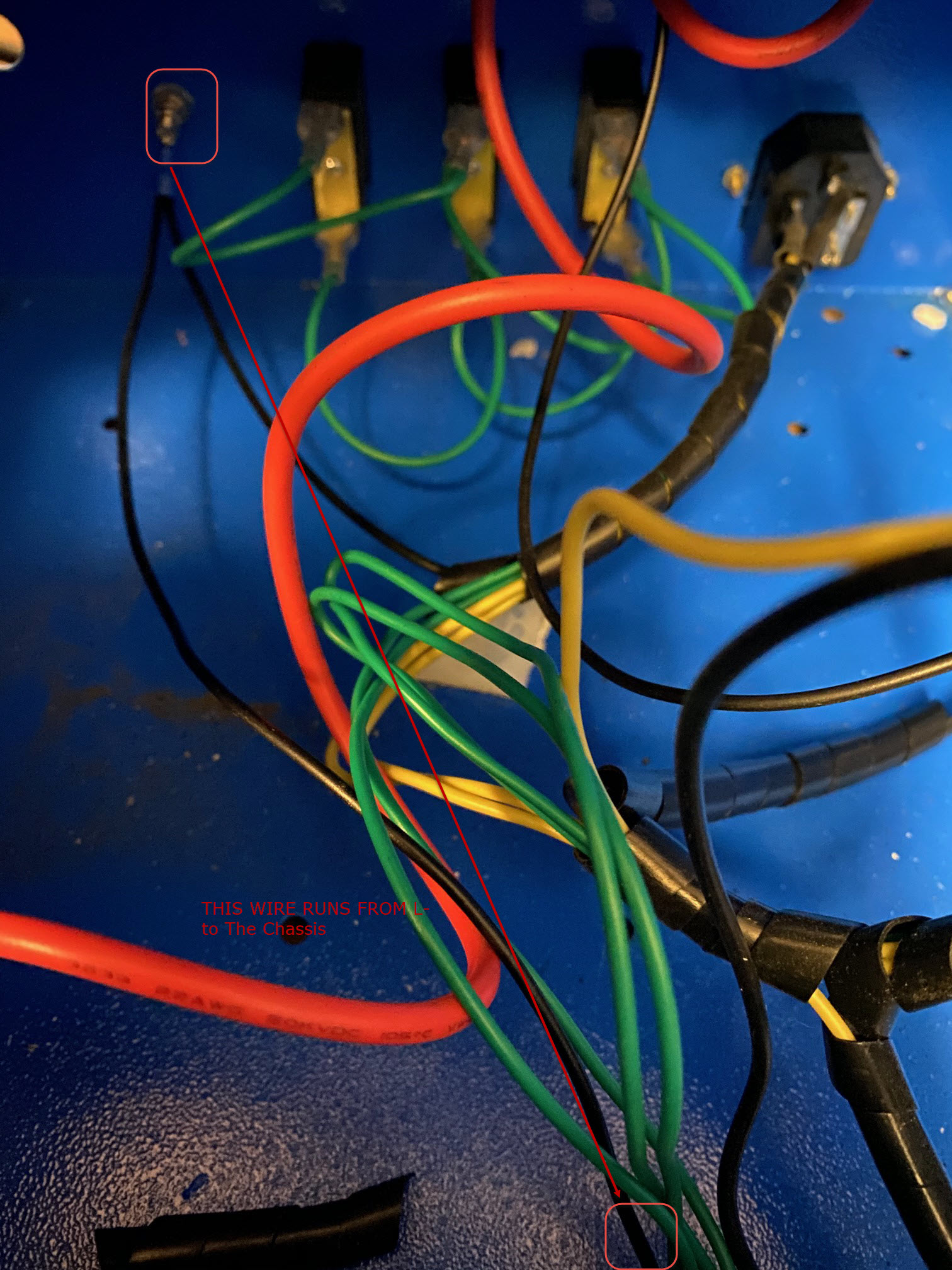
So I have read all the posts that say take the Black/Purple/whatever colour wire from the laser which goes into the L- on the LSU. My problem is the L- goes right to the chassis, there is nothing connecting it to the low voltage line on the laser. Instead the low voltage laser line runs into my Flyback transformer, then the output wire is run to FG on the LSU. Help everything is backwards.
Greeting Andrew and welcome!
Can you provide some pictures of your wiring?
Also pictures of the LPS connectors.
This may vary dependent on the type of supply you have:
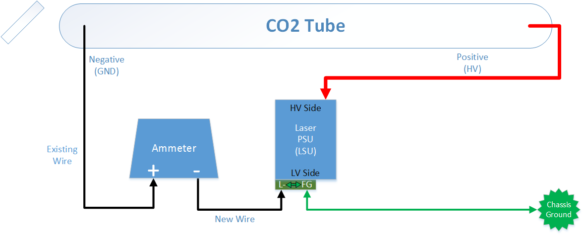
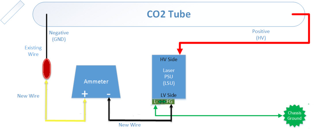
If you have the typical K40 LPS! ]the wire that comes from the cathode goes to the meter + and the other side of the meter goes to the - pin on left hand connector on the LPS.
DO NOT connect to the -L pin (unfortunate label) on the right connector of the LPS.
Usually the LPS meter ground piin is labelled L- or just -.
Pictures of your wiring and LPS will help us verify.
1 Like
So I’ve got it figured out. I don’t know what that thing on the sidewall inside the laser is (looks like a coil). Anyways the cathode wire runs into one end of that and then out the otherside comes a yellow wire which attaches to the FG PSU input. I ran the mA meter between the yellow wire and the FG using the FG input in place of the L- input (as this was running to the chassis). My thought is if L- and FG are a chassis ground then the PSU input should also be common. I tested it and worked - although I dropped my meter and it remains at 10mA constantly (new one on order).
I’ll do up a fancy diagram like this one and post as well. I don’t proclaim to know what I am doing so I may have fluked out here so take my advice or don’t I can’t really tell you what to do, but heed all the warnings that everyone has expressed over fiddling around with the Power Supply.
We still need pictures!
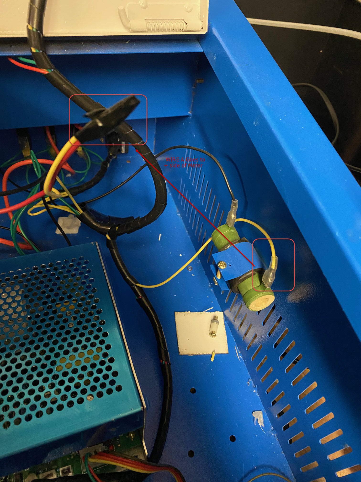

the green thing is a ballast resistor, some older machines came with them. Mine did but I removed when I replaced the laser PSU.
1 Like
Yes that is a ballast resistor and is not needed with that supply.
1 Like
So thing number 1: I can essentially remove the ballast resistor. Thing number 2: Did you see any issues with the way I hooked things up?
You can remove the ballast. If you have an ohm meter I would love to know its value.
Anything wrong with the wiring? Lol, I am not at a vantage point that I can make any recommendations one way or another. Does neatness count?
I assume that you will bolt down the LPS?