@Bodger Take a look at the manual that @mike_r1 linked to — this is a complete external unit with its own logic and has an enclosed driver, but given that you can connect the same wires to either logic or motor power there’s obviously an interposer between the input wires and its stepper driver. There’s no need or place for a logic level shifter here.
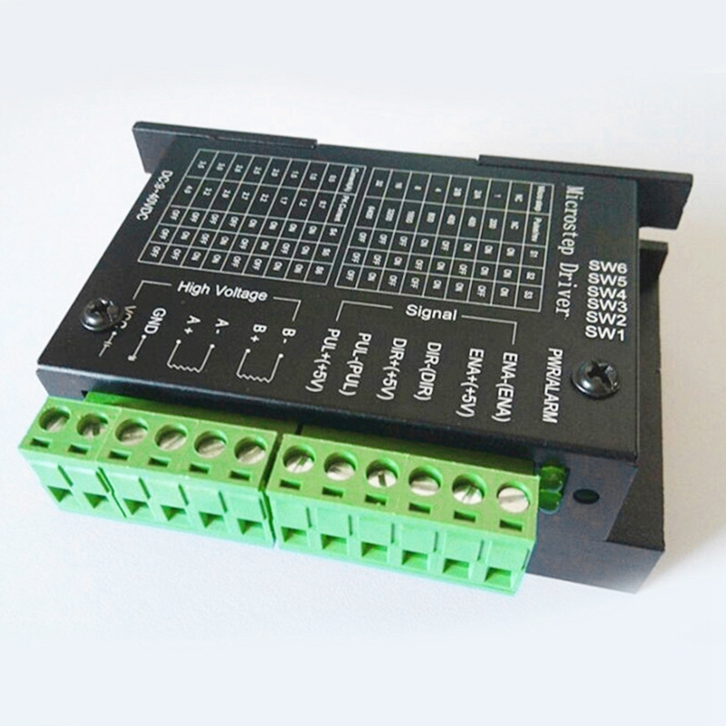
This stepper picture shows what a driver expects to see on the logic input and what it provides fot the stepper motor. It does require a 12 or 24v power supply to drive the motor.
@Bodger that’s not what @mike_r1 has.
The older “v1” of the project that he has looks like it had LV8727 stepper drivers in it; the board looked like a version I know of that doesn’t use optoisolators and takes the normal logic-level EN/STEP/DIR directly.
The new “v2” that he has does something different — re-read the thread and you’ll see it. You can see it in the manual he linked.
1 Like
@Arthur_Wolf, the controller has circuitry interposed between the wires and an internal stepper driver. This doesn’t hook up directly to the external stepper.

My reason for showing a motor driver was to show what was expected on any driver. I realise that is not what is fitted in this stoneflower printer. What I said about the smoothieboard is valid. M1 M2 & M3 on the smoothie are stepper motor drivers with outputs to the coils of the motors for X Y & Z. It seems from the information given that these all work.
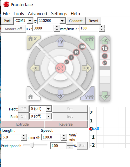
The smoothie shown on the manual page 18 does not have the final circuitry for a stepper motor, just the logical output which would be 3.3v. En Dir and Pul. The picture showing a meter checking is in the wrong place to check output for the extruder. It should be pins P0.21 P0.22 P2.3 and gnd.
On one of the pics Mike has drawn a blue circle around a set of logic pins. This is the wrong set, that is for extruder No2.
The G Code already asks for cold extrusion M302 P1… I think the problem if it is all connected up as it should be is in the Config file assuming the Extruder logic is OK and hasn’t been damaged by having a motor output at 12 or 24v delivered to logic pins.
Addendum.
M109 Sxxx is a “set extruder and wait” command so setting that to some arbitrary temp in Celsius should make the program think it is up to temperature. S10
M104 Sxxx sets temperature to goto as well. Set this low as well