TinyG2 (Arduino Due+gShield) weird probing behavior.

TinyG2 (Arduino Due+gShield) weird probing behavior.

Originally shared by Sebastian Szafran

TinyG2 (Arduino Due+gShield) weird probing behavior.

My TinyG2 (Arduino Due+gShield) adventure continuation, hopefully not a neverending story. This time I want to report weird probing behavior.

I had some problems during the first PCB autoleveing last Sunday but after few tries it went somehow successfull through all 60 probe points. So I thought problem has been solved. But yesterday I tried another Autolevel and also Touch Plate and it looks “Due live its own life”.

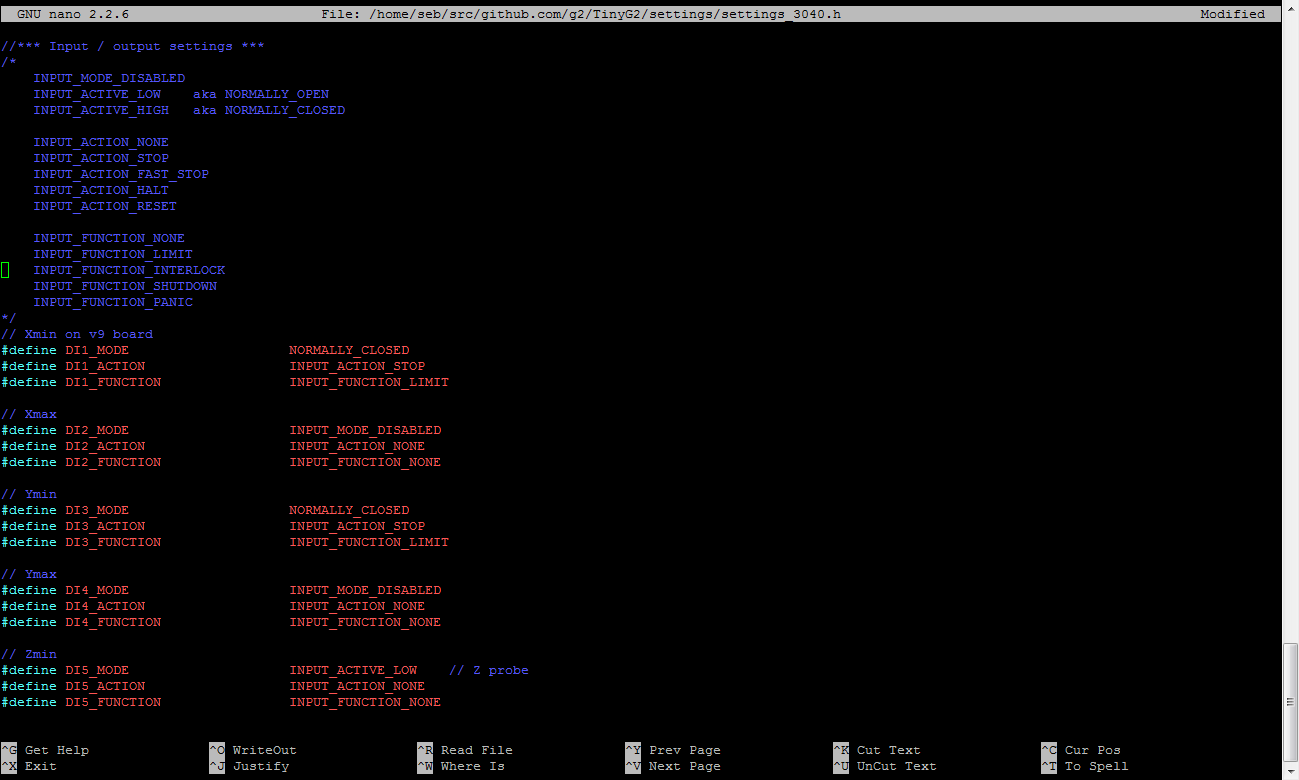
The probe pin is using Z_min_ (D18 pin on the Arduino Due) and according to the appropriate settings.h it is defined as:

// Z min
#define DI5_MODE INPUT_ACTIVE_LOW // Z probe
#define DI5_ACTION INPUT_ACTION_NONE
#define DI5_FUNCTION INPUT_FUNCTION_NONE

INPUT_ACTIVE_LOW is a NORMALLY_OPEN equivelent, which I would expect is correct for a probe. The probe pin (D19) should be held HIGH state (VCC = 3.3V for Arduino Due) until it touch the copper = gets connected to GND and changing state to LOW.

I connected GND wire to the tool (bit) and the Z_min_ (D19) PROBE pin to the copper clad. Started Touch Plate widget first and it randomly works/doesn’t work/works… Then I used an external pull-up resistor with relatively low value to force a strong pull-up for the D19 pin and it did not help. Depending on the D19 logical state (which depends on whether it was connected to VCC or GND few moments before) it works or it does not and as the D19 logical state will fluctuate if not continuously pulled-up to VCC or pulled down to GND this is the reason why it sometimes works and sometimes does not.

Then I simply connected a DuPont wire to D19 and started Touch Plate test. Z-axis went slowly down, as expected, until I touched GND with the other end of DuPont wire. But when I touched the wire to VCC the situation was exactly the same. So I can ‘trigger’ the probe by connecting D19 to GND or VCC - it does not matter. The same happens with autoleveling. It does not matter whether I connect the D19 probe pin to GND or VCC to ‘trigger’ the probe.

Using pull-up or pull-down resistor ‘forces’ the probe pin to a HIGH or LOW logical state and probing gets triggered immediately at Z-probe-max height.

Based on my experience current state of TinyG2 development does not assure that your machine hardware can be operated predictably. I had some travels into bed due to failed probing last weekend, causing some bits to crack and some bad words to go out of my mouth…

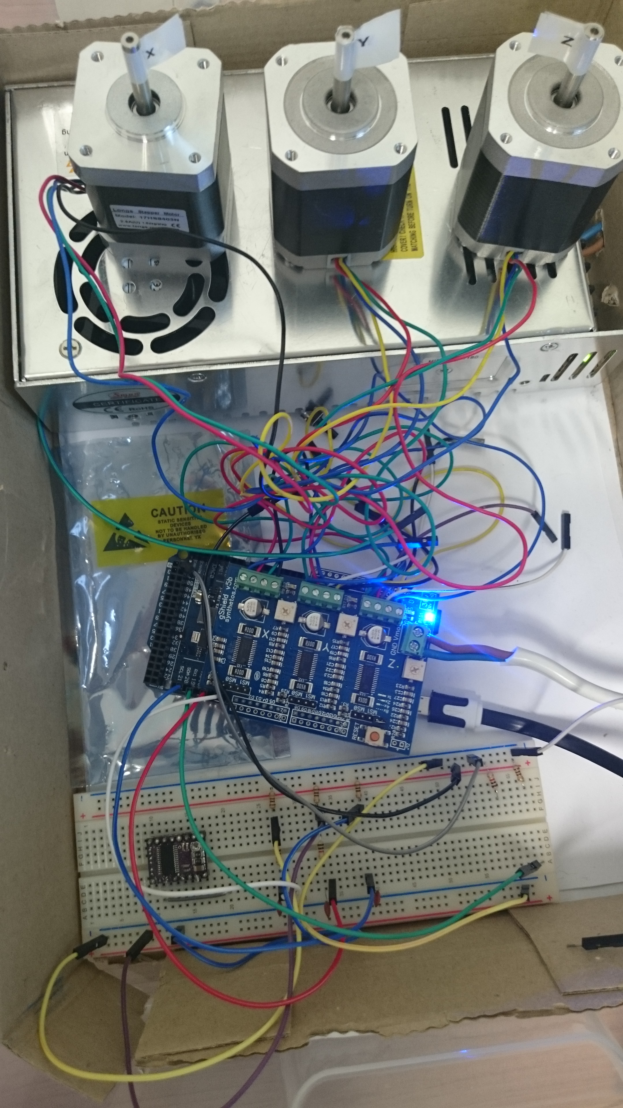
In order to be on the safe side I made ArduinoDue+gShield+3motors+ a bread-board simulating limit switches and probe and now I can test, test and re-test with motors running in the air.

The only question is:
When the ArduinoDue based TinyG2 platform will complete its experimental phase and become a production ready device for CNC hobbyists?

For my end stop limits I had to place capacitor between input pin and gnd. When I put scope on it could see the noise get eliminated. Before this my homing cycles were hit or miss.

Not sure if this would help.

You are in a sandbox that I have not played in, so my comments/questions are a bit generic, dated and maybe just plain incorrect:

  1. Your settings.h details - can you add a bookmark as to what setup process you are following? G2 wiki, G wiki? someone else’s’ notes (etc.)
  2. It is my understanding that G2, just as with tinyG, uses transition between states, high to low, or low to high to signal contact on the probe port. That was a change, a while ago, to solve the conundrum that NC switches were "more noise immune’ than NO.
  3. I see Peter’s comment and also wonder if multiple transitions due to ‘arcing’ of the probe in play here. Just touching two wires is never a clean process. T he downside of faster MCUs is that the raw bandwidth of the ports generally increases, better port filters may bee needed. There may also need to be more hysteresis(de-bouncing) on the port(s) in G2, for your particular setup.

BTW, I really like your testbed, may clone it! I’ll add that it is likely, if those are NEMA17s, that an old 60 - 100Watt Laptop brick may be more than adequate power for this; I am thinking about portability.

@Peter_Hanse ​ There is an low pass RC filter and an external pull-up connected to each of my limit switches on the breadboard, as well as on my machine. After I started using NC switches and added resistors and capacitors to filter noise, I see no problem with limit switches.

@cmcgrath5035 ​ You will find the settings.h related setting on the screenshot attached to my post. I did not touch other files. What surprises me is that after pulling up the PROBE pin to VCC it gets triggered, while it should be just logic HIGH and waiting to close the circuit by touching to GND.

Should I define the PROBE pin behavior elsewhere?

I also am seeing this exact behaviour nd have done across a number of builds. I may give the Capacitor on input pin a go, but I am pretty stuck with this too. I have similar craziness happening on homing as well.

@cmcgrath5035 Based on what is happening I am not sure if really a ‘transition’ state LOW to HIGH or HIGH to LOW is really the case here.
Simple test: connect PROBE (D18) to VCC via pull-up resistor (internal or external) and start Autolevel. The result will be immediate ‘trigger’ every 5mm (default is 5) at constant height defined by ‘clearance height’ value.

@Ben_Delarre After changing input mode to INPUT_ACTIVE_LOW for all limit switches (same setting as for Z-probe) my TinyG2 works as I would expect. My limit switches are of type NC (normally closed) and wired with pull down resistors in the following way:

  • switch Common connector connected to VCC (3.3V for ArduinoDue)
  • switch NC connector connected to input pin
  • pull-down resistor (any value between 1k-10k is fine, lower value = stronger pull-down) connected to input pin and GND

Z-probe is connected as NO switch with pull-up resistor, while the mode is INPUT_ACTIVE_LOW.

Great tip Sebastian! I will give this a go next week.