This post is long it and is a quick description of the wiring of

This post is long it and is a quick description of the wiring of my Peltiers cooling system asked for by a number of people. For more info on it look back in my post history.

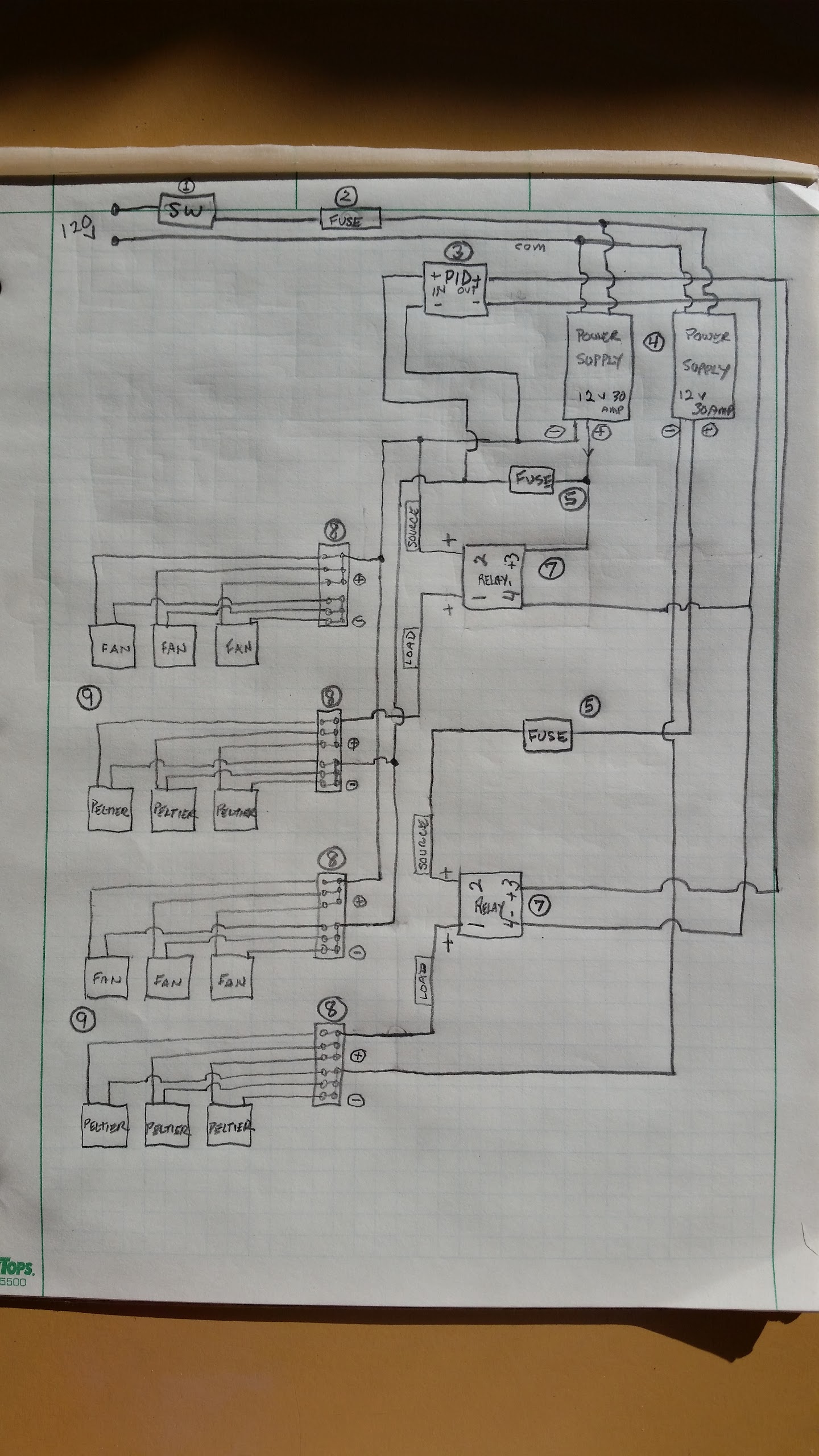
Here is the wire schematic for the two bank Peltier three pads 180 watt units I’ve talked about in past post. The two banks in mine (360 watts) give me about 250 ‘functional’ watts of actual cooling. I’ve used it when temperatures have been in the high 90’s (32 to 35C) without any heating problems and keeping the water within 1 or 2 degrees at all times. So far, no matter how long I’m running the laser. The current history is I have ran the laser for around 45 mins continuous on a raster file and maybe 20 min of a vector cutting 5/16 inch Popular in 95F (35C) temps . In fact, the cooler is only running about 50% of the time once it got to programmed temp.

One thing to watch for with refrigerated cooling is the dew point. I program the operating temp by looking at the current temperature in the room and program about 5 deg above that. However, as the day goes on or the temperatures change the dew point can change. I almost got caught one day so I watch it closely now with one of these cheap digital hygrometers.

I am not trying to keep 19 liters of water cool. I’m only using about 2 ½ liters in a closed and insulated system with a small mixing tank. That’s all. I think this works best for this type of cooling system. With a Peltiers there is no need for all that water. The only reason you use water is it is the cheapest and most efficient way to get the heat out of the laser tube and to the Peltier’s surfaces. There they pull the heat out of the water and draw it out on their radiating (hot) side which has a finned surface area attached and fans to clear the heat. It appears that 250 “functional” watts is a good number for the way I’ve set mine up.

List of parts:
Item 1 (1) 120v AC switch McMaster Carr #3431T1
Item 2 (1) Fuse holder McMaster #7687K11 (1) fuse #71385K527
Item 3 (1) JDL 612 (12v) PID temperature controller, LightObject
Item 4 (2) 360 watt 120v AC to 12v DC 30 amp transformers off of e-bay
Item 5 (2) Fuse holder McMaster #7687K11 (2) fuses AGC 20A 32V
Item 6 No item 6
Item 7 (2) 40 amp Relays ESSR-40DDC and heatsinks, LightObject (lots of cycling so I went higher amps.)
Item 8 (3) Terminal Blocks and jumpers McMaster #7527K48 and (1 pk) #7527K59
Item 9 (2) Peltier 3 fan and Peltier cooling banks 180watt input 126 estimated functional watts cooling each bank. See link for source.

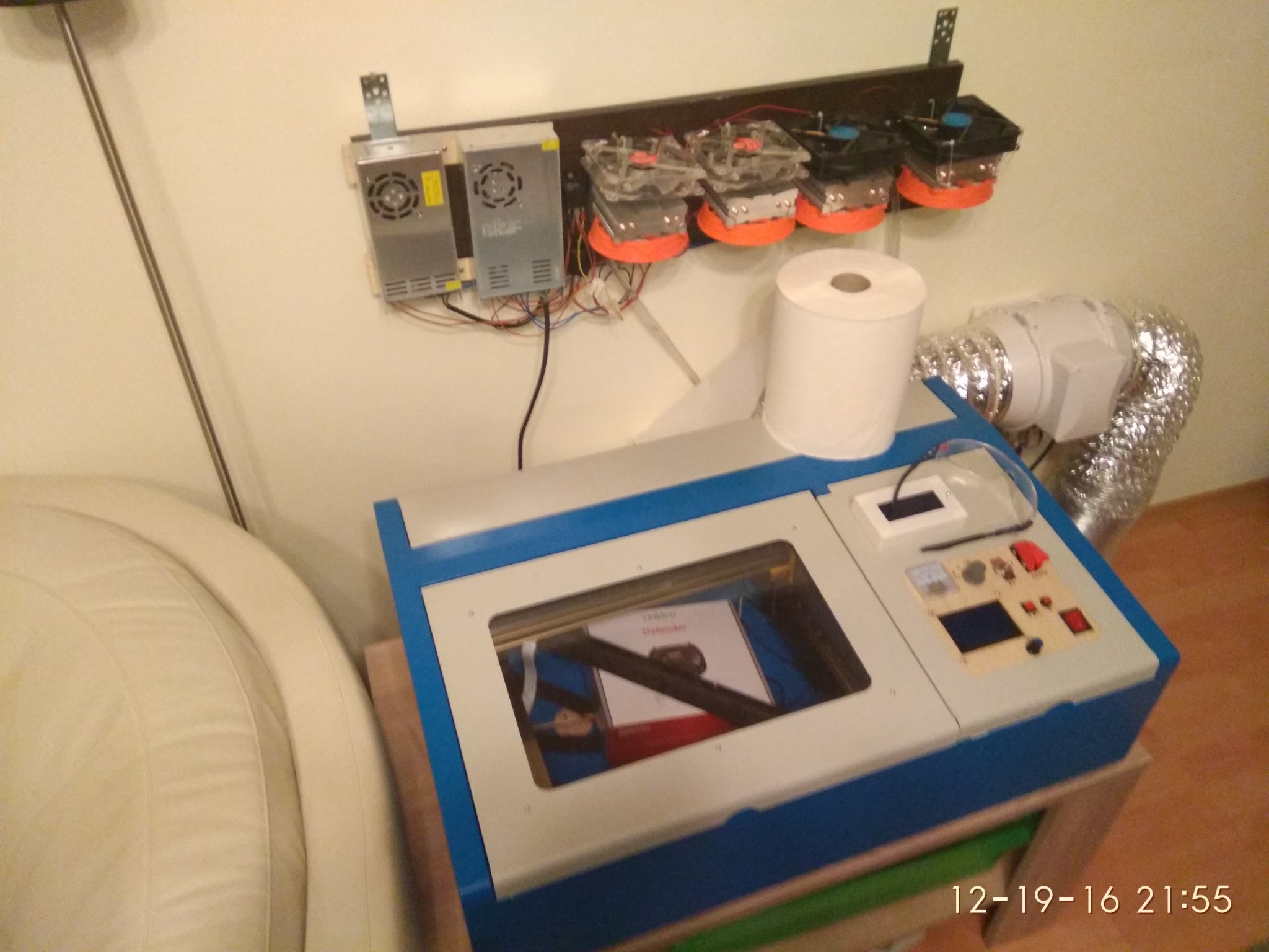
I have other electronics wired into my electrical box so it looks busier. I also bought a long terminal for ease of wiring and space. Below are links to :

Similar Peltier water cooler bank I used.
https://www.ebay.com/itm/180W-Semiconductor-Refrigeration-Radiator-Thermoelectric-Peltier-Water-Cooler-/263166880642?hash=item3d45f7eb82
Note: These come and go on e-bay so you may have to look for them in a 3 bank. There are bigger units but the PS are pricey over the 12v 30amp size which can be found on e-bay for $19 including shipping if you look hard enough.

How to properly wire the relay.

The relay wiring can be confusing so I suggest watching this video.

How to set the temperature controller… basic operation.

If you use the same PID I did it can be confusing. I ran across this video before buying one so to simplify things for me, I just spent a few extra bucks on this PID with all the bells and whistles.

@Steve_Clark thanks for this awesome write up. Makes sense…

Heh, I did not realize that there are SSR’s for DC… :). Why does DC need zero crossing
ANS: it doesn’t? I guess there is a MOSFET driver in them, hopefully not just a relay.
Mmmm I wonder if I could use them to run my OX spindle! Gona try…

I am still either confused or amazed. In previous posts you suggested that you were able to cool from an ambient of 90F to the 70’s F??? That is a large delta that I would not expect.

Which am I:

  1. Confused & misinformed…
  2. Amazed

:slight_smile:

@donkjr I would say it seems to be true assuming enough insulating is done to keep heat absorption limited as much as possible to the laser tube plus accepting the fact that water cooling with Peltiers is not the same process as using the five gallon bucket.

It’s apples and oranges. A smaller amount is needed and required to first quickly stabilize your desired operating temperature. And second, as a method to move accumulated heat out of the tube.

Any water mass beyond those needs will affect the performance, as that extra mass must be brought down to your programmed temp. and that could require a lot of cooling power.

In the case of a 5 gallon container, I most likely would have had to turn the cooler on the night before! So in order to get a reasonable and responsive performance level out of the system I reduced the mass to just enough to pull the heat generated from the tube and then be absorbed at the Peltiers. As long as the heat is taken out at a rate faster than it was generated at the tube… I was good.

It was a bit of guess work and playing with formulas found on the web. None really gave me a direct answer but kind of just let me know I was on the right track.

Looking at the large delta achieved it’s really limited only on my cooler by the temperature settings with the ratio between the lasers power output and absorbed line and tank walls heat verses the 250 watts of cooling power.

I’m not willing to try it, but I suspect if I set the PID controller to 0 deg C it has the ability to get fairly close. Likely one or more of the Peltiers would start freezing up and block the water flow though before it got there though.

Just so you know, ‘I think’ I might have been able to cool enough with about 180 functional watts of Peltiers but to be, safe I spent another 35 bucks getting me up to the 250 watts.

For our cooling needs in the laser we of course very rarely would ever have a delta of more than 25deg F as we are limited by the relative humidity with its affect on the dew point.

BTW - Here is a simple calculator for that.

http://www.dpcalc.org/

Also - SSR DC…I used the higher amp by recommendation of a friend who is and electrical eng. His point was because the system is cycling alot they will run cooler last longer.

I’m using 4 Peltiers of 135 actual electric watts each (146w rating afaicr), on 4 alu blocks in series, on a secondary pump. I can get the 20 liter tank (4.5gal?) Down by more than 1 deg Celsius/hour, maybe around 1.4°C/h. Nothing is insulated. When cutting at 10ma with the default K40 “40W” tube the water stops cooling and keeps the temp steady, maybe raise by 0.1-0.2°C/h. I have 2 pumps in the tank, the one that came with my K40 runs the Peltiers and another one with 146l/h actual debit runs through the tube, measured at the return to tank hose, these pumps heat the water too. Temperature is measured via a DS18B20 network at the tank, intake and outlet of the tube.

Never occured to me that by knowing the water volume, the number of °C you heat in a period of time can show you how much watts of heat the tube “loses” To tired to do the math but maybe you get the point :slight_smile:

Yep, the contraption above the laser gets the job done. Old pic, the laser was in piecer ready to receive the new gantry back then.

@Mircea_Russu Your post shows why I opted for a small water mass. I can pump the heat out that smaller amount of water quite fast and maintain my cutting temperature with less than a 50% duty cycle on the Peltiers while under average cutting circumstances.

During heavy duty cutting my expectations and experiences have being the same just a higher duty cycle percentage.

With a breakdown of a cooling system using less water it can lead to that water heating up faster. One unplanned on advantage to having two cooling banks with separate PS and SSR is redundancy.

If one goes down I still have cooling. I have installed lighting on my panel that shows the Peltiers have power and each bank is cycling on and off as needed. Also an audible temperature alarm also comes with PID controller.

@Steve_Clark thanks again for the build advice on the peltier design. Sorry for another long post.

Maybe this is my summer build.

I had planned to reduce the capacity and close the cooling system. That to me has a few advantages:

  1. Less mass to cool
  2. Closed system is cleaner longer, less frequent changes. Less coolant to replace
  3. Electrical isolation of coolant and laser

Disadvantages of this build for me:

  1. Must find another 6 amp peak (thoretical) AC in the shop.
  2. Another build distracting me from using the machine, although you did all the hard stuff.

A. Have you measured the AC current you are drawing? Would be interesting to see the actual AC load this presents.

Notes/questions on your build summary:

Parts list: your “360 watt 120v AC to 12v DC 30 amp transformers off of e-bay” cited in your list above is actually a switching power supply vs a transformer :).

Looking closer at the schematic to learn its operation I have some questions :

B. Are you controlling both banks with the PID. In the schematic I do not comprehend how the top bank is controlled?
a. In the top fan bank the plus side is connected to the minus of the PS for that bank. The ground side of that bank is open [fans do not run]?
b. The plus side of that supply goes through a fuse and connects to the minus side of the first peltier bank. [fuse protects the second banks fans?]
c. The plus side of that supply goes to the minus side of the second fan bank?
d. The plus side of the first relays output goes to the minus of the supply.
e. The plus side of the supply goes to the plus side of the first relays input [that relay stays on?].
f. Should the two banks be wired exactly the same. I expected that the:
f.a. Fans are on all the time?
f.b. Both banks are controlled the same and in parallel?
C. You suggested that in addition to the PID you had other indicators where are those located in the circuit.
D. Is there a DC pump connected in here somewhere?

Design suggestions:
I. I wonder how much noise is conducted/radiated. I am not so familiar with the DC SSR switching characteristics. I imagine with peltiers the inductance is low so switching noise is minimal. In any case we might consider putting a line filter on the input to minimize noise injected into the source power.

II. Adding snubbers to the DC SSR’s as suggested in a previous post.

@Steve_Clark Thoughts on this peltier module? Seems the plumbing would be simpler?

Looks like if I assume I have all the peripheral parts (fuses etc) I could do a 370 Watt for under $300?

@donkjr Great post Don… your finding my errors and I’m learning more about electronics! The switching power supply does create some noise I hear it in the radio on a AM station. Maybe because my power supplies or mounted a couple of feet away and in a earth grounded steel box it has prevent problems. I was having some rare problems with rastering but I’ve been adding some shielding to my C3D area and the issue has not came up lately.

[B.] THE SCHEMATIC HAS ERRORS. I’ll review it directly by tracing the wires in the unit to make sure there are no other errors. I’ll need to change that picture. Anyone know how? I thought I saw a way to delete it but I’m not seeing how to replace it.

[ a,b,c,d,e,f] THE SCHEMATIC HAS ERRORS. Looks like I posted it WAY TO SOON! I’ll red line it and redraw the whole thing. Wow…I thought there might be one or two errors but not this bad!

[fa] When the main power is on the fans and the cooling come on. You can’t run the laser without them on.

[fb] Yes they run parallel and are controlled the same.

[C] Yes I’ll add them in the new schematic drawing.

[D] I have a AC water pump it is connected to a duplex AC outlet on the side of my electrical box and it only come when the main (#1) switch is turned on. There is also air pump plugged in there has its own on off variable speed switch.

”a line filter on the input to minimize noise injected into the source power.” I like it… but do not know anything about them or (for sure) where to put in the (AC?) source power.

I looked up line filters. Same question about “snubbers” I kind of know what they are… where in the circuit would they be placed and what kind would you suggest?

I have other work today but will try to review and redraw the schematic in the next day or so. Thanks for your suggestions and review Don. We know the cooler works right we just need to tune the circuit and get the schematic corrected now.

I was drawing up a schematic of the water side of this cooler but that will have to wait now.

@Steve_Clark I’ll make you a deal! You draw up the water side and I will do the electrical side and deliver a source file for you :)??

I will add the component suggestions …

@donkjr
Deal! The Panel lights that let you know everything is working are just 12v LEDs I happened to have. One is to the fans power and 1 each to the 12v power to the Peltiers.

The nice thing about the PID I used is it has a auditable alarm you can program.

@Steve_Clark will start on it tonight :slight_smile:

Bump on this thread. @Steve_Clark did you ever get around to that second wiring diagram? I’m about to embark on a similar PID peltier journey

@Brogan_Murphy take a look at this. I don’t think that @Steve_Clark ever did a final review?

https://plus.google.com/+DonKleinschnitz/posts/GctVUPr38Pv