This is the start to Ring Rap openSCAD. So far we have a way to change out the cross section of the rim, a standard way to specify rim size (using ISO diameter, as that is the best way i could find), Specify spoke number and hole size (will add taping holes in the blocks.
I am structuring it so that all variables for the printer are stored in one file, so you don’t have to mess with finding hard coded numbers… although there will be some.
The repository is at:
let me know what you think.
I have spurts of motivation. and this happened to be one of those times.
What is used for linear bearings on the z axis?
edit< never mind found it
Well, it is kind of messy. i still need to go though and do comments.
It is on my to do list. I need to decide how it will be printed… Also on my todo list is to reduce part sizes…
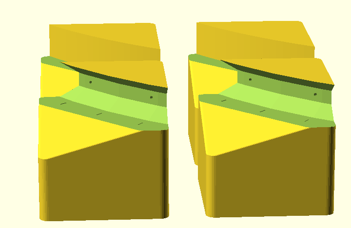
I am thinking an 1cm thick piece of the arc to check the profile, and a 10-15 degree arc piece for checking diameter.
As for the height increase, are you talking about from the ground, or above the ring.
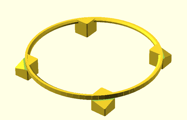
If it is above the ring/feet i was thinking that the feet would double as the corners of the bed, so I would add the spring stand offs for bed leveling there.
FYI, when you start printing heavy things you may want to consider a different bed leveling system. as those springs will sink when 2kg of plaster is added.
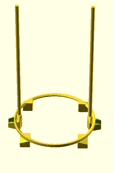
I think you are referring to the amount of plastic on the vertical pole. That distance is parametric, currently it is set to 100mm, and the legs are set to 70mm, it is possible to change those to any positive number.
If i am incorrect let me know.
Edit: also i need to work on the clamp to allow the builder to grab onto the rod. Currently it would be friction fit.
Will do… currently this would be the base. (it has alot of extra print material that i need to remove) When i make that part i will make sure to make that distance variable, along with several others.
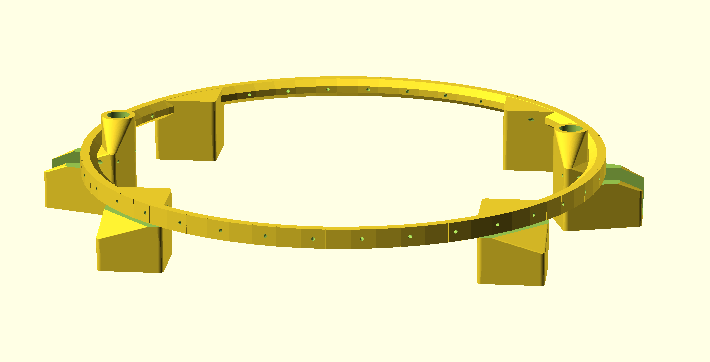
Oh, one really cool thing i built into this scad model (that i don’t see in the original ring rap files). The bike rim spoke holes are “drilled” into the part. Every part is placed on the rim at a specific angle, So when you mount it to the rim (using screws) you will get perfect alignment every time you assemble it.
Two questions, how is this reducing the rigidity? do you mean removing plastic?
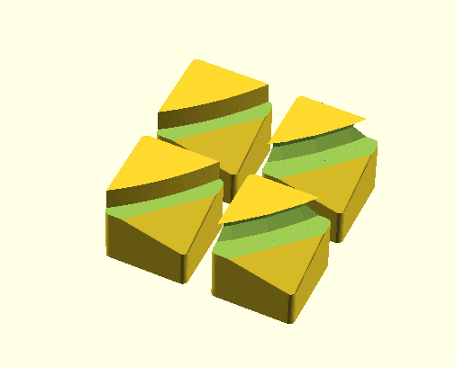
Second i did a commit with the new “Test pieces” i need to do some testing to make sure the code actually works well. but for now it is on git. The STLs for some example test pieces are now on git. The profile is that of a random rim i found on the web…
Updated, also reduced the foot height to reduce print time (no need for 40mm of extra plastic, i think it will reduce it even more however), Added nut traps, and bed holes for the bed leveling screws. And added instructions to the SVG to walk through how to make a new rim contour.
I think that pretty much finishes the base, now onto the print ring. I am still thinking that a drive shaft will be cheaper/lighter extra steppers, what do you guys think?
Lol we posted at the same time, but there is now instructions for how to make rim contours. I dont know if you have used inkscape in the past, but it is free, and makes alright DXFs. I am just putting each contour on a separate layer. If you use a different tool you need to make sure you have no Splines after the export. curved lines do not import into openSCAD, you need to turn them into line segments and corners. My instructions explain how to do that in Inkscape.
Also i just learned that layer names cant have blank spaces…
Fiance wants to go out tonight, but when i get the second ring done i will do a new set of renders, generate all of the new STLs post an update.
Quick question, I know you said that you wanted to mount this to a wall, do you want a printable bracket that goes over the contour of the rim and then screws to the wall?. it would not be a hard part to model.
FYI i am moving some of the stuff around in the files… i am trying to avoid having a monster main file. I will be breaking things up into a files for different rings (base, middle, Top) and bringing some of the customization into build config file. (like the number of pillars/ location of pillars)