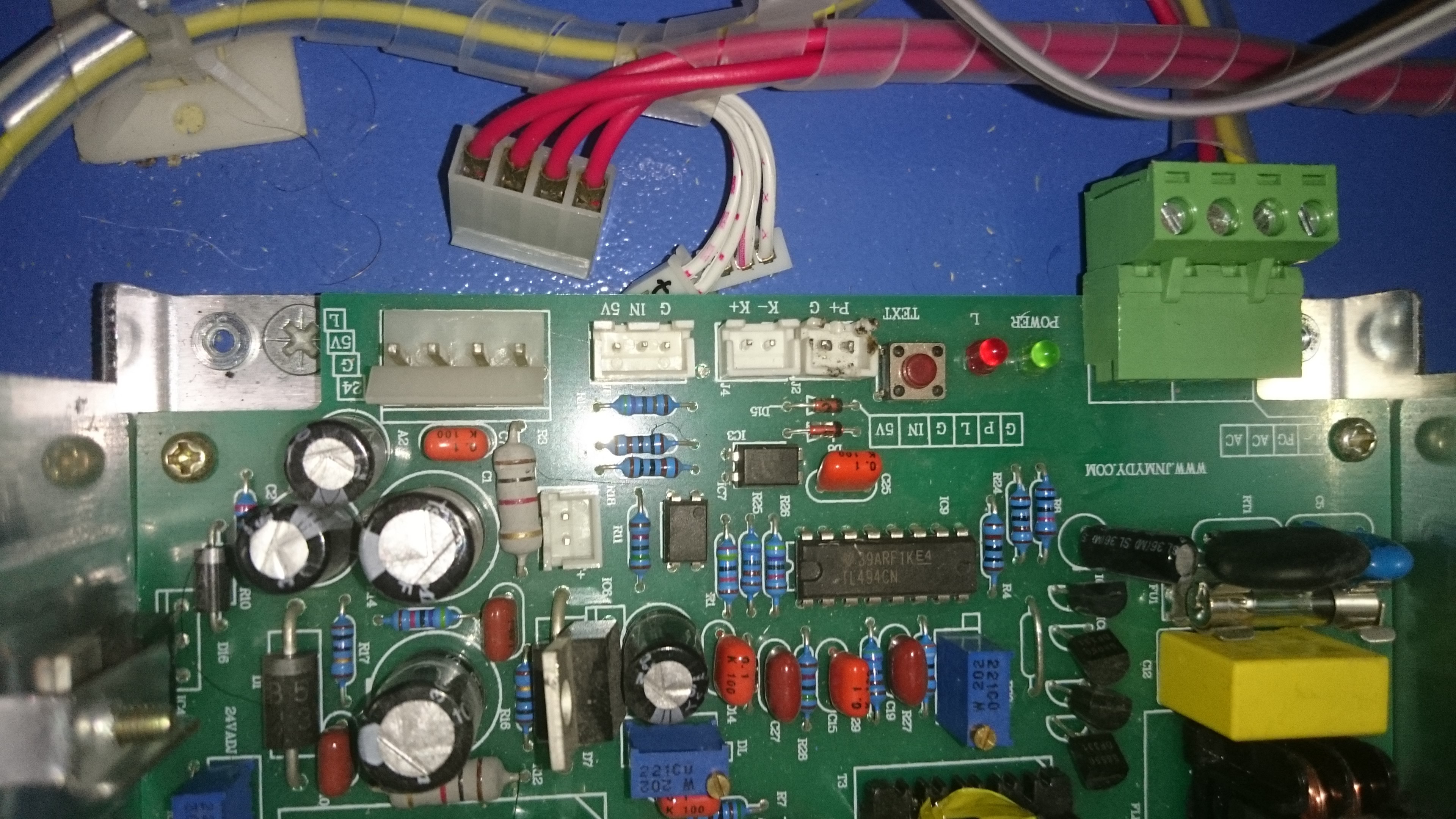
This is my K40 PSU. P+ and G has been bended and soldered by default. I unsoldered those pins to allow interlock switches (door, water flow, temperature sensors) connections.
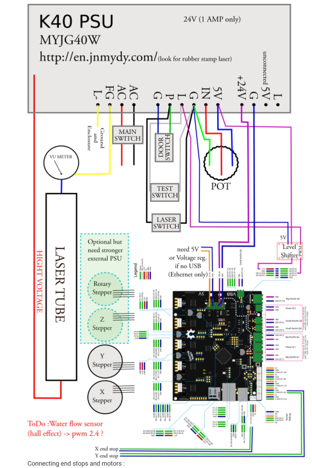
Does the diagram work in way that L current value will be ‘directed’ by Smoothie PWM while POT sets the maximum current (ceiling = 100% PWM) value for the laser tube?
or
Is it better to connect Smoothie PWM to IN and remove POT?
or
Smoothie PWM1 connected to IN and Smoothie PWM2 connected to L and directed separately?
or other possibilities?
@raykholo should be able to help since he has allready donde de con región and the PSU is the same. Do you have a level shifter? Not sure if he used it or not
I have all needed parts, just want to know the right setup before wiring it. I think the setup with POT and PWM is quite OK and allows additional control over max current level.
Don was asking me to try this… Ok so L (outer end of the red cable large terminal) to a MOSFET (-) which will pull it to ground when switched. Power my board using the 24v and Gnd from that cable as well. Leave everything else connected as it was before
@raykholo L to MOSFET = Laser Enable when connected to GND, right? And if I remember well, you don’t have potentiometer wired, but PWM connected to IN instead. Current value controlled with PWM Sxxx.
‘Leave everything else as before’ - do you mean Moshi connections as template? I don’t use Moshiboard anymore, actually cannot use it, as I have already cannibalized connectors from it.
I think other connections like stepper motors, limit switches and interlock are quite clear. The most important is to choose the best (or most commonly used) option for laser control.
@sszafran Yes, the L turns on the laser when it is pulled to ground. So when Smoothie tells the mosfet to turn on, it pulls the L to gnd and the laser fires.
I mean, the other things that were plugged into the PSU (the switches and pot) should stay plugged in to it as before. Obviously the endstops, motors, and the red wires are going to the various places on the new board.
Me? I do have the pot disconnected and have my board sending a PWM to the middle pot pin. But the idea is that you do not need to do this.
Thanks @Alex_Krause and @raykholo . I keep the pot connected to 5V/IN/GND. The only question now is: is it better to connect PWM to IN (Ray) or L (Alex)? Both seem to work, that means not only IN but also L is PWM capable. How is IN and L related during laser operation?
@Alex_Krause is laser power proportional to L voltage in a whole range of ‘minimum effective laser-on’ voltage up to 5V? And I wonder if the characteristics using IN will be the same.
So I have to clarify: if you want to drive the laser with L only, then when you are in the config, you define that MOSFET as your pwm pin. In that case you keep the pot connected and it sets the ceiling, as you said. My way - level shift a pwm pin to IN, disconnecting the pot entirely. L is used with a separate MOSFET as a switch controlled by M3 and M5 to enable and disable the laser. Bigger gCode file. My way - the test fire button does not work. I did want to remove the pot from the equation completely because now I am confident in the absolute S percentages I am using to cut. Ie S0.85 to cut acrylic, every time, consistent. 10 and 5 mm/sec for 3mm and 6mm respectively.
@sszafran depending on the result you are looking for I have seen a difference when connecting the pwm pin2.4 directly and the mosfet output of pin 2.4. while connected to the mosfet I saw a power ceiling of 7ma as opposed to connecting the 2.4 to the breakout pin my max mA is that of the potentiometer and using laserweb power control it is scaled between those to. Another observation I noticed was mosfet output kept the tube in a ready state more efficiently allowing me to use 0-100% to engrave grayscale better. Running thru the breakout pin I notice I have to bump up the minimum power in laserweb to around 10% or the tube won’t fire with enough power to engrave the lower end of the of the gray spectrum. I will shortly be testing my laser ouput using the large mosfet instead of the small one to see if it will raise the power ceiling to the potentiometer output
I too use pwm on the large mosfet to control the L line and have left the pot in place on the IN line. It’s nice as it allows power tweaking during a job. The only caveat is that I had to lower the pwm frequency a lot to get a linear response from my psu.