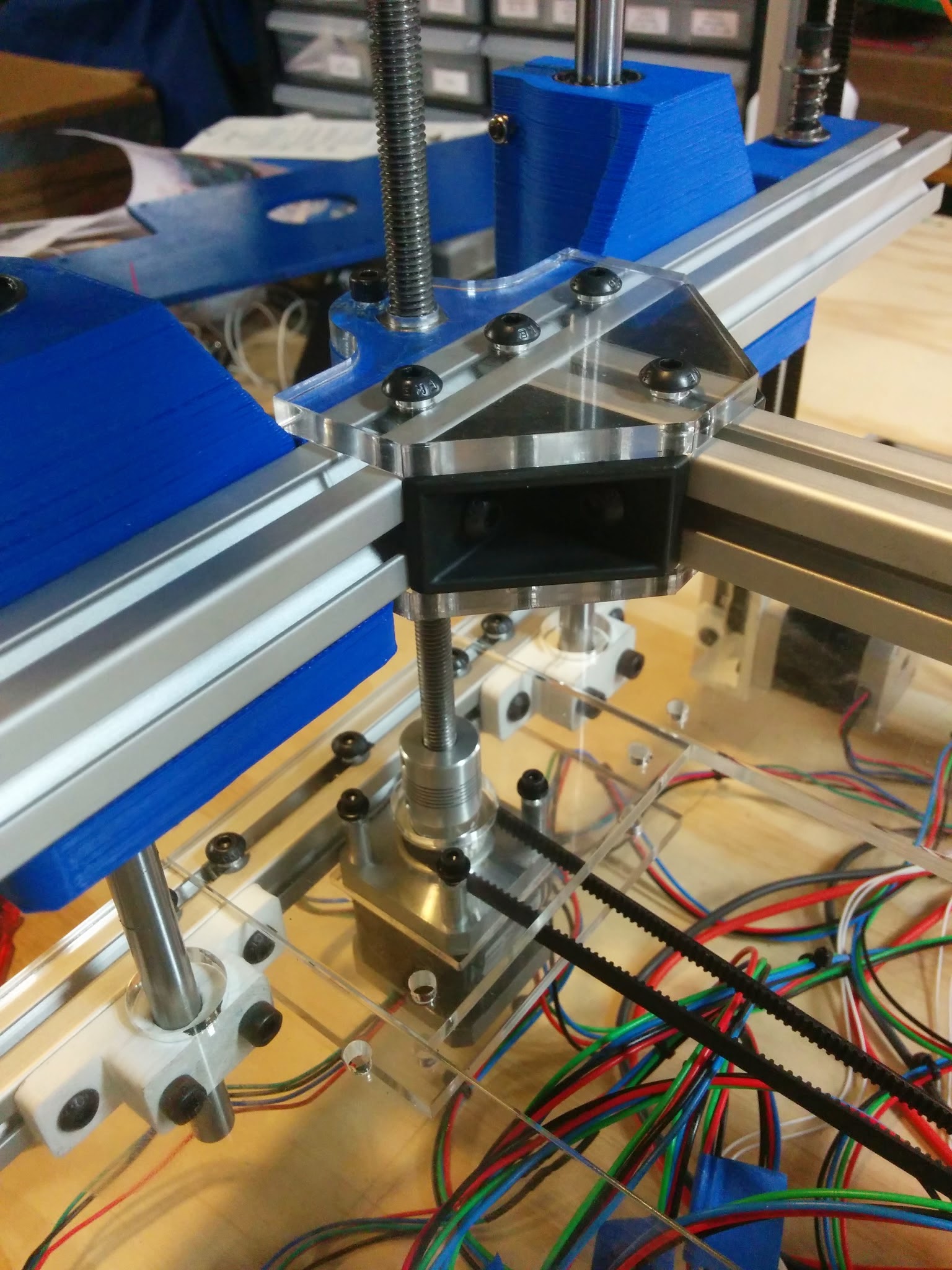
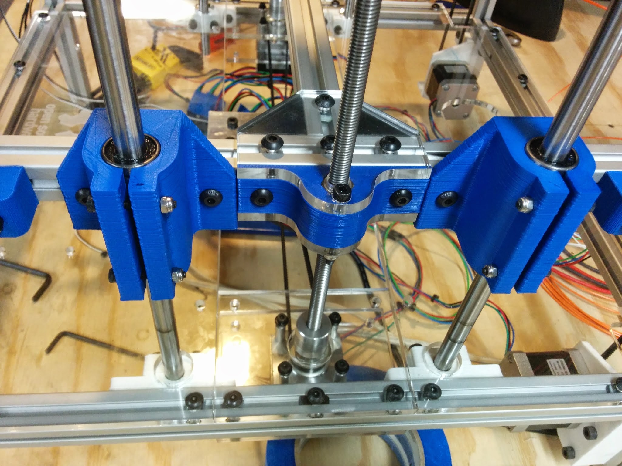
So, as some of you predicted, my Z-axis is giving me hell. The lead screws will randomly bind up at certain places along the screw and the steppers will make a god-awful noise. Sometimes, once the motors stop, it’ll unbind enough to travel again if I tell it to. Other times, it’s just stuck. I tried shortening the center aluminum extrusion on the bed assembly as I determined it was a bit long for the spacing of the 2 z-steppers, but it only helped a bit. It still gets stuck now and then. I’ve gotten it to home maybe twice without it binding up.
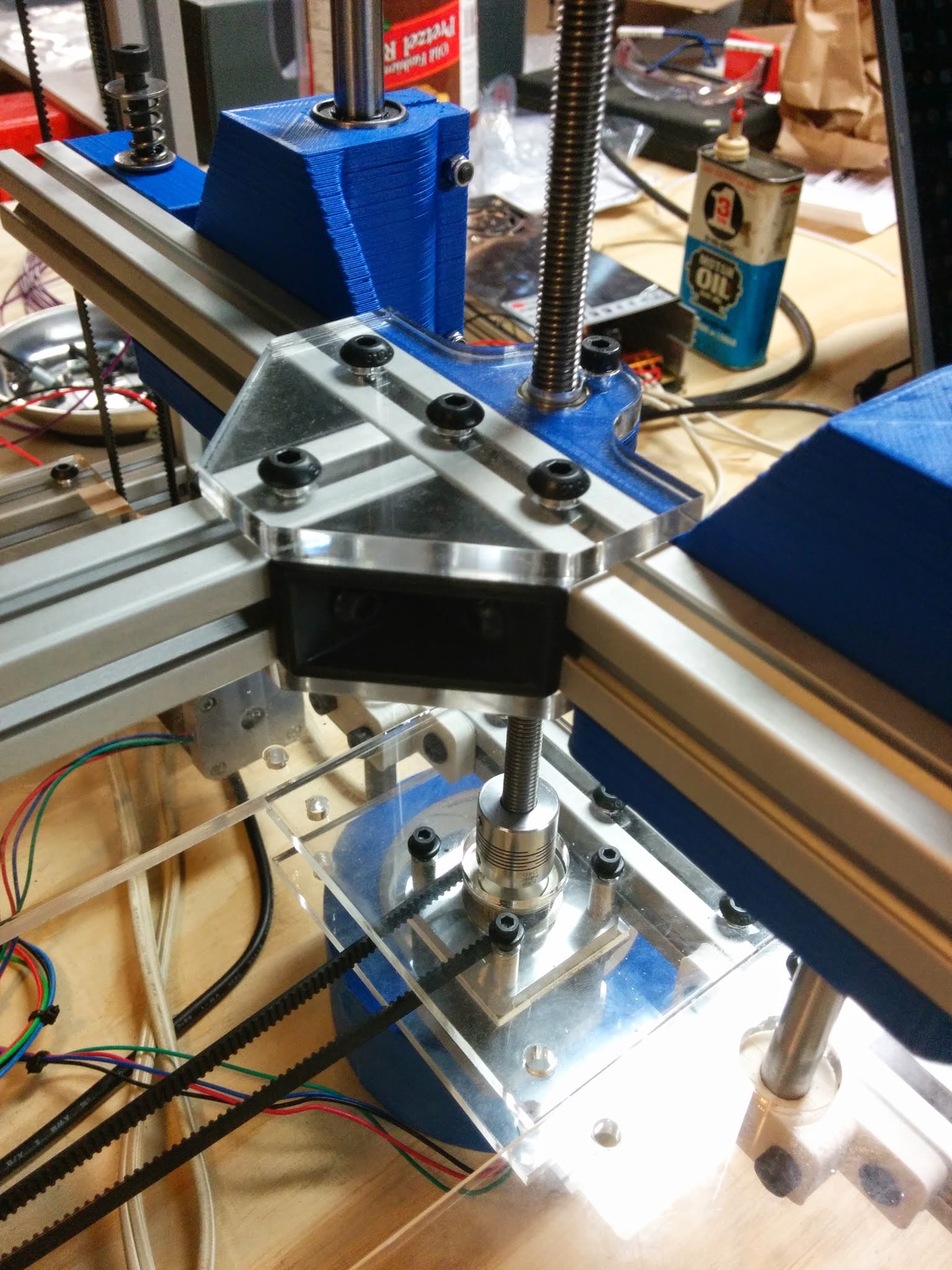
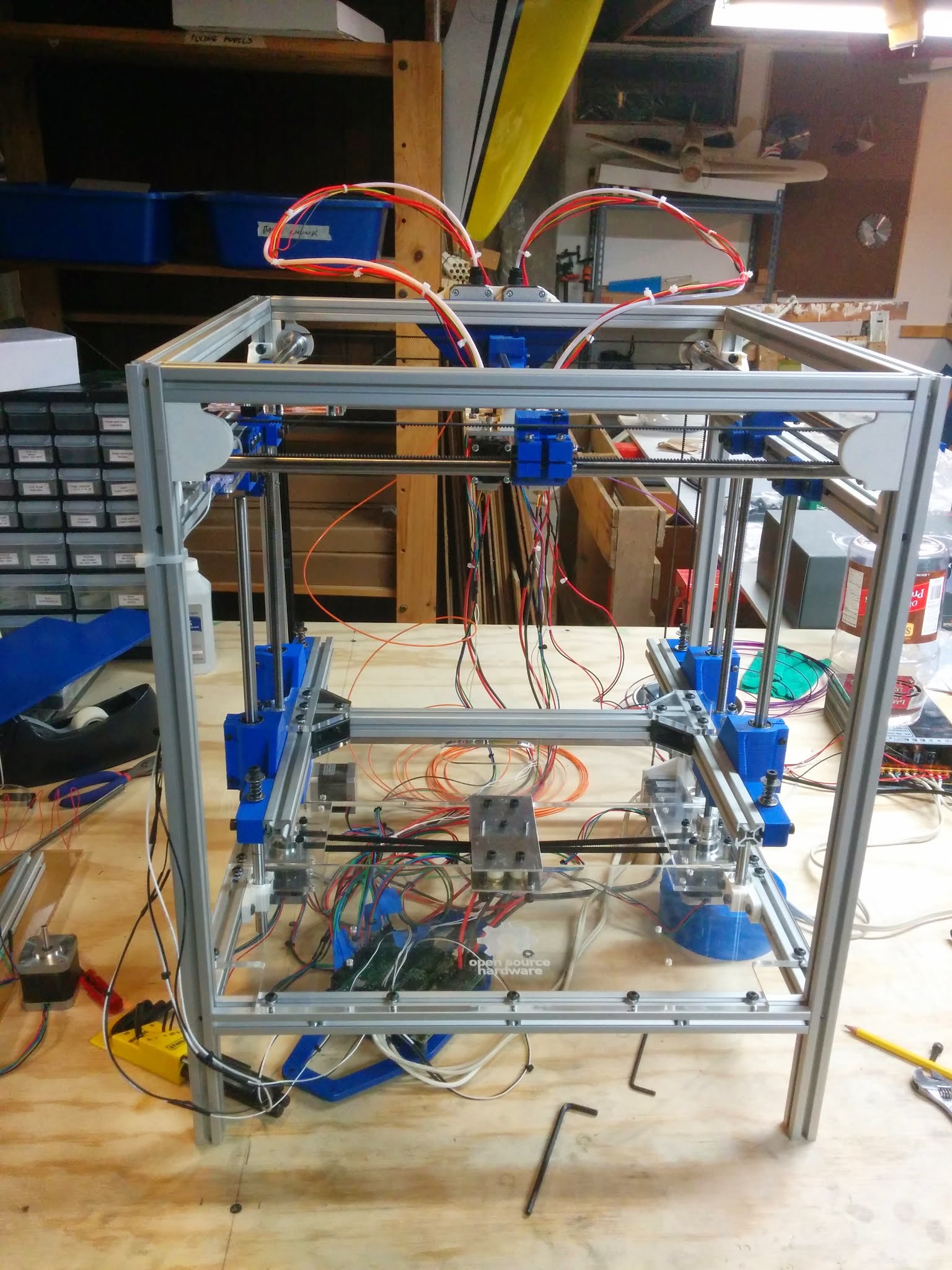
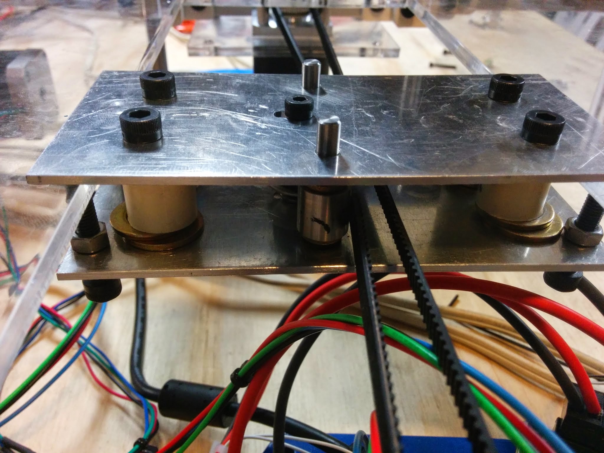
You can see in the pics that I have belted the 2 steppers together with a tensioner in the middle. this helps A LOT as one stepper will help the other out if it’s encountering too much resistance. The tensioner is just 2 idlers and a timing belt pulley that’s free to spin. It takes out the slack in the belt, as I was unable to find any smaller ones that fit.
Any ideas on how to salvage it this design? I’m really close to just throwing in the towel and going with @Jason_Smith 's original design. It’s really frustrating.
(On a more positiove note, the rest of the printer appears to work perfectly!)
I agree aligning 4 rods vertically will be a brute. Tolerances of the printed z bearing brackets would have to be perfect because you are stacking 4 tolerances at least. It could be done, but I don’t think its worth it.
I can reef on my bed with zero motion and it only has 2 rods. I print daily and haven’t re-leveled on over a month.
It does help slightly if I let the top ends of the smooth rods float completely freely. However, the resistance that’s causing the issue is not in the linear bearings. The bed moves up and down very nicely without the screws in place. The resistance has to do with the screw-nut interface. The resistance changes based on the rotation of the stepper and the position of the screw the nut is currently at. When I go to check this by just spinning it with my fingers, sometimes it’s really easy to spin. Other times, it’s really hard.
I’m looking at prices of the original design, and can’t find MTSRA12-410-S56-Q8 on misumi. I can find RMTSRA12-410-S56-Q8, however. Is there a difference?
i’m sure that if you look at the treaded rods while they’re turning, the axes in witch they turn will not be bang on… look for a anti-backlash nut method… easy to construct.
Redesign the nut brackets so they float in the xy plane. Don’t allow the nut to turn as it floats, or you’ll get artifacts in the print from the tiny changes in z. The acrylic (?) Plates you already have look like they should be able to carry the z axis load, you just need a way for the nut to float between them.
@Erik_Scott when I added the Super-Z mod to my #Printrbot (height increase to ~23 inches) I found that the design to constrain the top of the threaded rods was a poor choice because the el cheapo non-trapezoidal imperial threaded rods they shipped me were far from straight (the banana shape was blatantly obvious). I allowed the tops to move freely and that fixed the side to side ribbing I was seeing (smooth rods are straight, but over such a long height they can still be forced to flex a bit by such poor threaded rods).
However, the smooth rods do have a high straightness tolerance so I did not allow them to move (as you have done) because doing so would defeat the purpose of having them in the first place–keeping the X/Y in place while the threaded rod adjusts the Z.
So, if allowing the smooth rod tops to wiggle reduces your binding problem, then I submit that either A) your threaded rods are not straight, or B) your smooth rods (which are likely very straight) are not properly aligned. I would also second @Eclsnowman 's remark about allowing the nut to wiggle a little in the X/Y because the smooth rods should be keeping the platform fixed in that plane.
My threaded rods are unconstrained at the top. I am very aware of why you shouldn’t do that.
I’m not sure how I’d make the nut float, but I think the spring I have below the nut may be too strong and not slowing the but to tilt with the curve of the threaded rod. I’m going to give that a shot first.
@Erik_Scott you can do just x by making the nut trap a slot along x. Then align the screw in y by making the mount shorter and placing it in the correct location along the bed extrusion.
It would be possible to make a square nut, double height, that fits into a slot for x and y.
Or you can use a thinner screw which allows for flex.
There is also a fitting called an oldham coupling, which allows x and y travel while rotating. If you axis slides without resistance up and down (read: smooth and nearly frictionless) and the nut can move without resistance on the screw alone, then the oldham coupling is what you need.
Admittedly, I had to “break in” my z axis when I first assembled my printer my lead screw would occasionally bind similar to what you describe, but after oiling and realigning the screws, and running an hour of g code to move the bed up and down, it became silky smooth.
I took out the springs and I get no binding whatsoever. Unfortunately, this also causes the nuts to occasionally ride down in the hex channel I have for them and not actually lower the bed due to slight resistance in the linear bearings. I added some lighter springs that barely exert any force when the nut is in the ideal position, and I once again got problems. Sometimes it will bind and sometimes the nut will just ride down compressing the spring until the linear bearings decide not to hold it anymore.
So basically, I needed to give the nut room to rock a bit to account for the threaded rod being not quite straight. Fixing this, however, isn’t that easy… Very frustrating.
I think I’m going to be going with your original design, @Jason_Smith . I can’t find the exact lead screw you specified in your BOM. Would you be able to point me to an equivalent one by any chance?