I had noticed this before on simplifying gcode with the ‘segment option’, that the sides of my object can shift (I used values of 0.5mm). I blamed this on the tolerances of my CNC, but I also noticed it on my laser.
Now that I was playing with dogbones, I now understand why this happens.
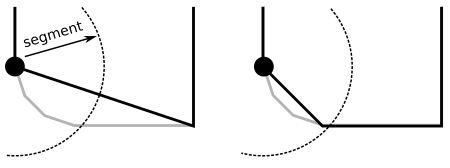
On the image in the left, the first point is shown. All vertex nodes that lie within the ‘segment’ length will be merged. This includes the left vertex of the longer line at the bottom, making it crooked. In my view the ‘segment option’ should only remove small details, not distort the large scale features.
By checking if the next segment will be long, the merging of last vertex in the cluster can be prevented, generating the picture on the right. I arbitrarily chose 4 * segment length, but might be enlarged further.
fix:
diff --git a/src/lib/cam.js b/src/lib/cam.js
index 4893ef4..9b80618 100644
--- a/src/lib/cam.js
+++ b/src/lib/cam.js
@@ -320,7 +398,8 @@ export function reduceCamPaths(camPaths, minDist) {
         let newPath = [path[0]];
         for (let i = 1; i < path.length - 1; ++i) {
             let sq = distSqr(path[i], newPath[newPath.length - 1]);
-            if (sq > 0 && sq >= minDistSqr)
+            let nextLengthSq = distSqr(path[i], path[i + 1]);
+            if (sq > minDistSqr || nextLengthSq > 16 * minDistSqr)
                 newPath.push(path[i]);
         }
         newPath.push(path[path.length - 1]);
The “length” of a segment is no good measure to simplify a line. I would suggest to use a Douglas-Peucker algorithm (it is relatively easy to implement). The deal is to ensure that the maximum projected distance between the real line and the simplified version stays below a given threshold. On the figure on the left, we easily see that the projected distance is much bigger than on the right. This gives a much better control on the maximum error the simplification may allow.
In my view, within LaserWeb the ‘segment option’ was intented to prevent clusters of small segments that appear due to an operation, most often in corners. I do not think it was ever intended to be a real simplify algorithm.
I agree that Douglas-Peuker, might generate better approximation, but this can (will) suffer from the same problems as above. Basically the only guarantee of DP is that all lines remain within a certain limit. So even the long lines could shift up to this limit. The currently implemented solution already stays within the DP limits, just not with the minimal number of vertices possible.
What I proposed above, guarantees to keeps the large scale dimension exactly in place, while only influencing the clusters of small segments. This is what I personally care about the most. That I might have a few vertices more than the optimal solution is less of an importance to me.
Edit:
I am personally mostly involved in CAD (i.e. lots of straight lines), so the clusters of small segments in corners are the most prevalent to me.
For people that do more of the ‘freehand’ kind of stuff, there a proper simplify based on e.g. DP will have benefit, but I think this should be a separate action on its own. The input should first be simplified. Not just the g-code afterwards, as is done with the ‘segment option’.
The segmet option was a simple solution to reduce the amount of gcode lines (=calculation duration) that resulted from very narrow points. By setting it to 0.5mm, you basically say that you can life with 0.5mm precision (of each point). What you need depends on your machines precision. That’s how it is. It’s a question of balance between gcode size and details. If you need more details, you have to accept bigger gcode (or vise versa).
@Kire_Pudsje: In your example, we are talking of about 0.3mm failure of the left corner when segment length is set to 0.5mm. If you set the segment length to 0.1mm, it would be about 0.06mm failure.