I was using previous versions on my main laptop. Then set up the newest version on a laptop dedicated to my sculpfun s9 and s30. Before, the engraving process would go from bottom left to top right for all vector graphics in the file. Now, it functions the same as it would for engraving images and focuses on one group of graphics at a time. I’m, honestly not sure which is more efficient (it only covered the soace between elements once when moving from the conpleted element to starting the next closest/chosen element), but I am curious. And if the blanket process from bottom left to top right is more efficient, how do I get it to go back to running that way for vector graphics? I’m a bit confused by the differences and could use some clarification about this if possible.
I was the author of much of the advanced optimisation code. In 0.7.x there was optimisation of raster operations, which got lost when 0.8 was announced and was re-introduced in a recent 0.9.x version.
In essence, in 0.8.x all the elements in a raster operation were converted into a single bitmap. So if you had a small raster element at the left of the bed and a small raster element at the right of the bed, then it would burn them as a single image and the head would sweep the full width of the bed. What happens now is that each set of overlapping raster elements is treated as a separate image, so that in this example it will raster one image with short quick sweeps and then make one move to the other side of the bed and do the second image in another set of short quick sweeps. This can save a lot of time. Personally I always have this turned on - I have not seen any negative effects.
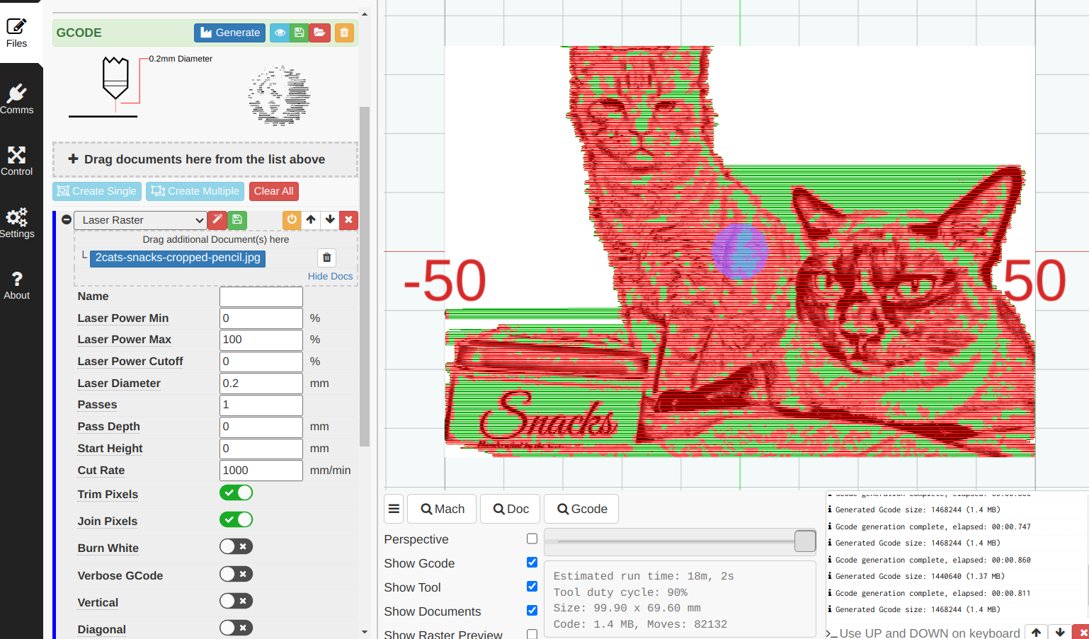
There are also various other optimisations:
-
Burn Inner first - designed to stop MK from e.g. cutting a big piece before cutting a hole in it with the risk that the big piece moves or drops and the hole gets cut badly. Personally I normally have this set.
-
Group Inner Burns - when you have multiple parts on a single piece of material designed to try to burn one part completely before moving onto another - so if you get a shift because e.g. the head hits the end stop, you get fewer discards. Personally I normally have this set.
-
Reduce Travel Time - the most basic optimisation which sorts the elements into a sequence which moves from burning one element to the nearest unburnt element - this is not necessarily the fastest possible route, but it is normally way way way faster than burning the elements in the sequence they are in the SVG file. (In MK 0.6.x the optimisation functionality didn’t exist, and I used to spend hours manually sequencing the elements. I didn’t write this functionality.) This optimisation makes the biggest difference. Personally I always have this set.
-
Burn complete subpaths - when this is turned off, the Reduce Travel Time will select the nearest unburned node - and this node could be in the middle of a line (non-closed path), in which case it would burn half the line, and then later burn the other half of the line. With this option turned on then it selects the nearest node if the path is a closed loop, otherwise it will only consider the ends of the line as a starting point, ensuring that the line is burned in one continuous burn.
-
Merge passes/operations - with these turned off, MK burns each operation in sequence for the first pass, and then repeats for any operations with passes > 1. Merge operations means it can switch between cut/engrave/rasters/image elements as needed to get the shortest travel time. This optimisation makes the 2nd biggest difference. Personally I generally have this set. Merge passes means it burns all passes of one operation before moving onto another - but it also means that it burns each element multiple times before moving onto the next element - and I find that this can create extra charring and a higher risk of a fire, so personally I normally have this turned off.
-
Splitting rasters - this is the functionality I was talking about above.
I hope this explanation helps.
Ah, I see. That makes a lot of sense. I think the raster splitting function might be a solid optimization. At lwast in terms of the runtime estimations. Ex. For something that takes up a 200mm x 300mm sheet without raster splitting estimates roughly 20 hours (and will finish in 5 to 7, I think). Where other projects of a similar size that I’ve run recently have time estimations more like 3 or 4 hours (and will finish in about 75-80% of that time, so roughly 2.5 to 3.5 hrs, I think…) Will put some items to the test soon and report back.
I don’t know what you are burning that takes 20 hours, but that seems excessive to me.
What power do you set on the hardware and what are your op settings? I will see if I can give you faster settings that will burn the same.
That’s just the estimated time. The actual time was around 6 hours, I believe.
Even 6 hours is a long burn. My offer to see if I can optimise your settings is still open.
Well, for my engraving, I am running at about 60mm speed at full power and an area 3.5"×14" takes about 3 hours to engrave. With cutting, a 4mm piece of wood takes 1% speed at full power with about 5 or 6 passes to cut through cleanly. Depending on how many lines are involved, this can take another 3 hours…so 6 in total. The estimation is usually about 20 or 30% longer than the actual time. Any other details I can offer?
Taking 5 or 6 passes at 1mm/s to cut 4mm wood suggests that your beam is not in focus. I would say that this is about 10x slower than it should be. (I cut 3mm in 1 pass at 3mm/s or 4mm/s.) Does it cut in less passes in some areas of the bed and need more passes in other areas of the bed? Or is it equally slow in all areas?
Time estimates for rastering are based purely on the rectangular area, whereas the scans themselves only cover from the leftmost black-pixel to the rightmost one and so are often shorter and quicker than estimated. I have suggested that iterating each line to find the first and last pixel (approximately - actually iterate 8 pixels at a time and test for zero) would be pretty quick but this has never been implemented.
Regarding raster time, I don’t really have all the information I need to look at the rastering time, because I really also need to know the DPI, but I can have a go. You say that a 6 hour actual burn (3 hours raster & 3 hours cut) is estimated at 20%-30% more, the estimate was probably between 7.2 and 7.8 hours, and assuming that the cut estimate was pretty accurate, that means that the raster estimate was between 4.2 and 4.8 hours against an actual of c. 3hours. 14" is c. 360mm so a 60mm/s sweep takes 6s. 4.8 hours is 17280secs, so that means c. 2,880 sweeps in 3.5" which is a DPI of 823. 4.2hours is 15120secs and 2,520 sweeps in 3.5" which is 720DPI. These are odd numbers because they are not a nice divisor of 1000, so image quality can suffer. If this is a raster of SVG vectors, then I cannot imagine you choosing this, but it is possible if this is the native DPI of an image.
However, a wood raster at 720-823DPI @ 60mm/s seems a VERY deep burn. For comparison I typically run raster / image ops at between 250mm/s and 350mm/s and at step 2 (i.e. 500 sweeps per inch) - so you are burning about 6-10x more than I do for a raster. Again, it could be a focus issue.
Summary: There really seems to be something wrong with your hardware setup.
P.S. When you say “full power” what exactly do you mean? 99 on the digital display or 12mA on your mA meter?
Its a diode laser, needing multiple passes for cutting jobs is quite normal, even when focussed. @CPUnltd understands focussing (see other posts) so I’d be looking to the material being cut.
Plywood and composites like MDF often cut very poorly on diode systems, all depending on how the glue responds to the near-uv of the diode. If it is translucent to UV it scatters the beam and your cut ends at one of the glue layers instead of going through.
Add in cheap ply with internal defects (gaps) being filled with glue etc and things get worse.
Get the right material and it’s different, I have some 5mm marine ply that always cuts in a single pass.
BUT! I also have some cheap salvaged 3mm ply that will cut eventually, but takes many passes. And I bought some ‘high quality’ modellers ply (1.75mm) that never cuts. The whole sheet lights up as the first glue layer diffuses all the power. I ended up marking on the laser, cutting by hand.
Ah - sorry - most Meerk40t users have K40s, and I made an incorrect assumption that this was what you have.
I don’t think you need to apologise, I was making the same assumptions at first ![]() , lots of users here assume we all recognise every machine by name, but that’s not (imo) humanly possible… I only remember the Sculptfuns are diode machines because they spammed me on YouTube.
, lots of users here assume we all recognise every machine by name, but that’s not (imo) humanly possible… I only remember the Sculptfuns are diode machines because they spammed me on YouTube.
PS the calcs for raster speed are spot on!
That is totally fine. I get that.
Ok, this is a bit OT since it’s a LaserWeb thing, but I wonder if Meerk40t has a similar option.
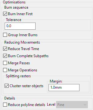
LasweWeb has two basic modes for rastering, controlled by a burn white flag, the goal of this is to control whether whitespace in a raster is done with G0 or G1.
For tube lasers (K40’s etc) the advice is to leave it on. This makes the entire job run in G1 mode, with the laser power set to 0 for the whitespace, at the cutting speed. I believe (this is before my time on the project) the rationale is to protect the tube from frequent power on/off cycles.
For diode/fibre systems burn white can be disabled and all the whitespace moves are now travel moves, depending on what is being rastered this can make a big difference:
This is a raster with it on: 23 minutes
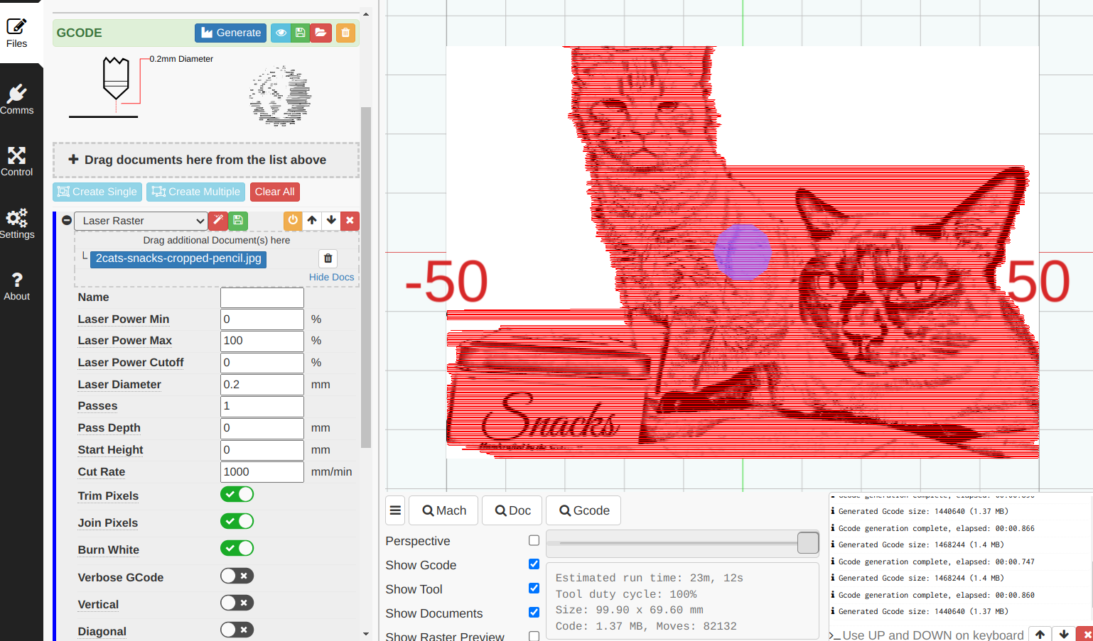
And Disabling reduces this to 18 mins. All other setting unchanged.
The green/red is LaserWeb’s way of showing travel vs cut moves.
The estimate given for the burn white version is quite accurate. But for the travel white version it gets less accurate, the real time will be longer.
Laserweb makes no allowance for accelleration/decelleration, and it can make a big difference on a cut like this with plenty of short travels. I’ve done some testing on this, and implementing accel/decel mapping into the time estimate is really desirable, but beyond my capacity to implement.
I do think this is a neat feature that is good, and can make a serious difference to cut times. And worthy of mention ![]()
I believe that is currently set properly on my machine (though Inciuld be wrong) as the machine “jumps” to its new position when it goes from one raster process to the next. The only time it doesn’t do that is when the rasters are grouped together. Then it will travel the same speed over all areas engraved and unengraved within the confines of the outer left and right edges of the designs to be engraved.