Pulling my hair out. I had an issue where my RGB strip (standard strip, non addressable LEDs) was flickering when brightness was reduced. I was led to believe this was an interrupt issue with my ESP8266.
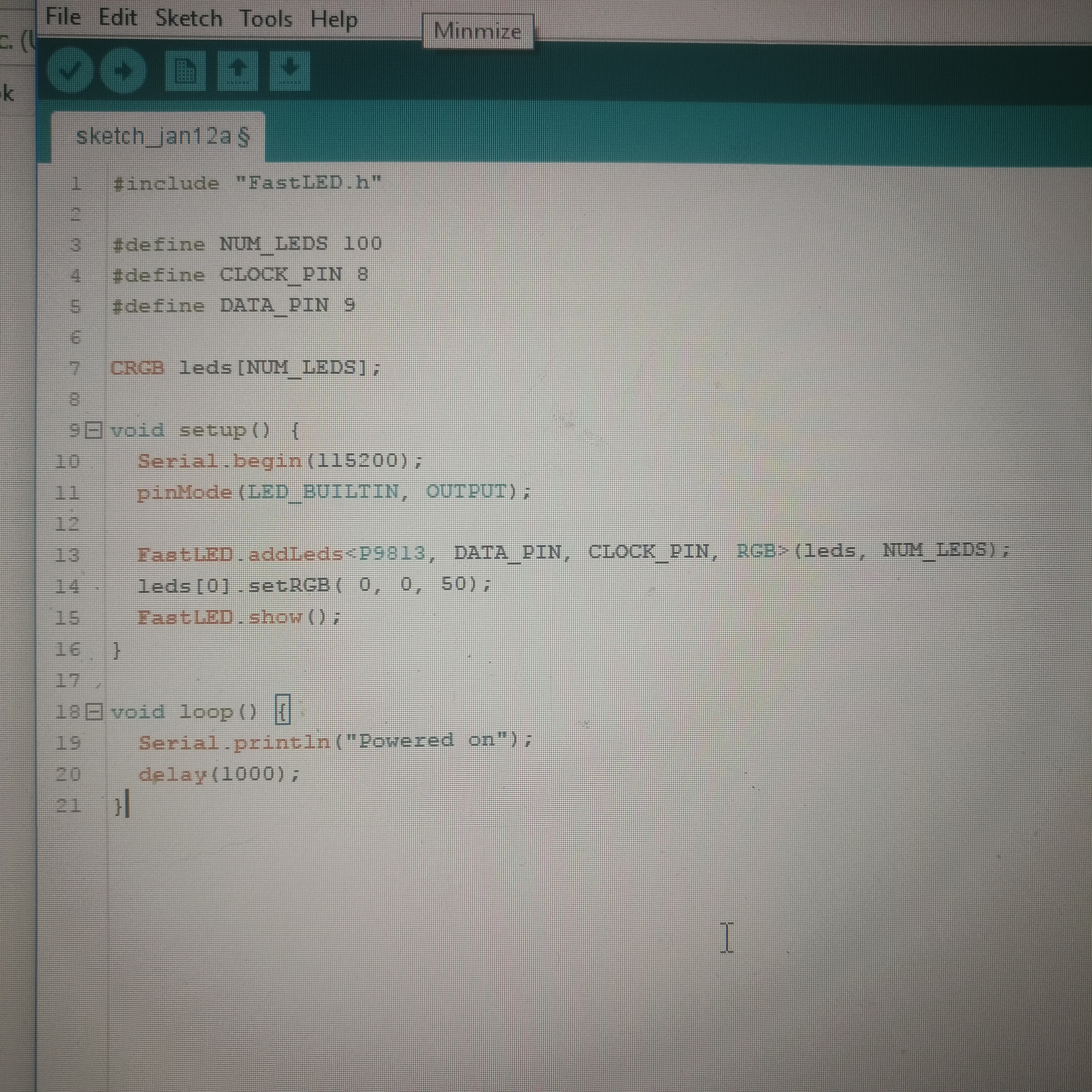
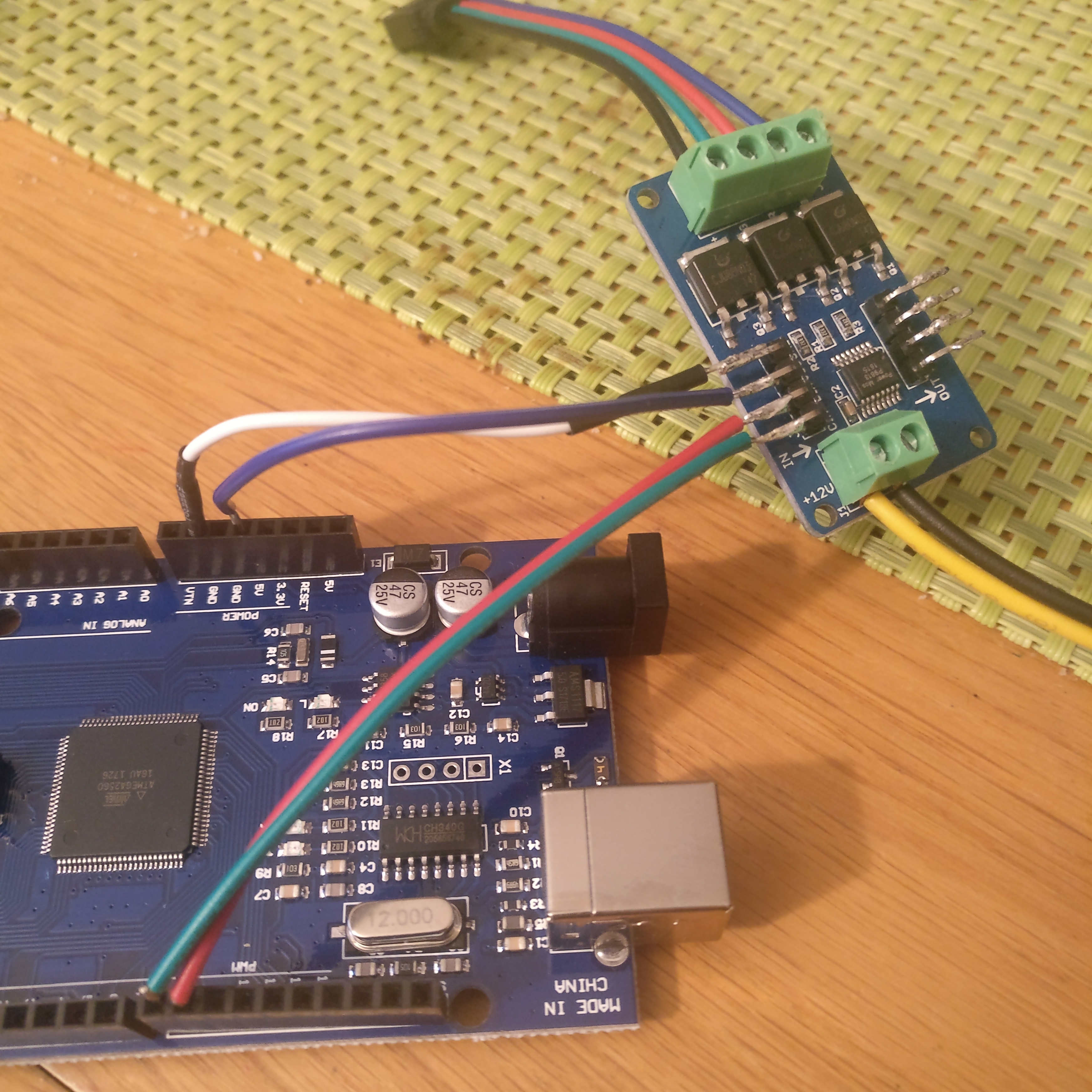
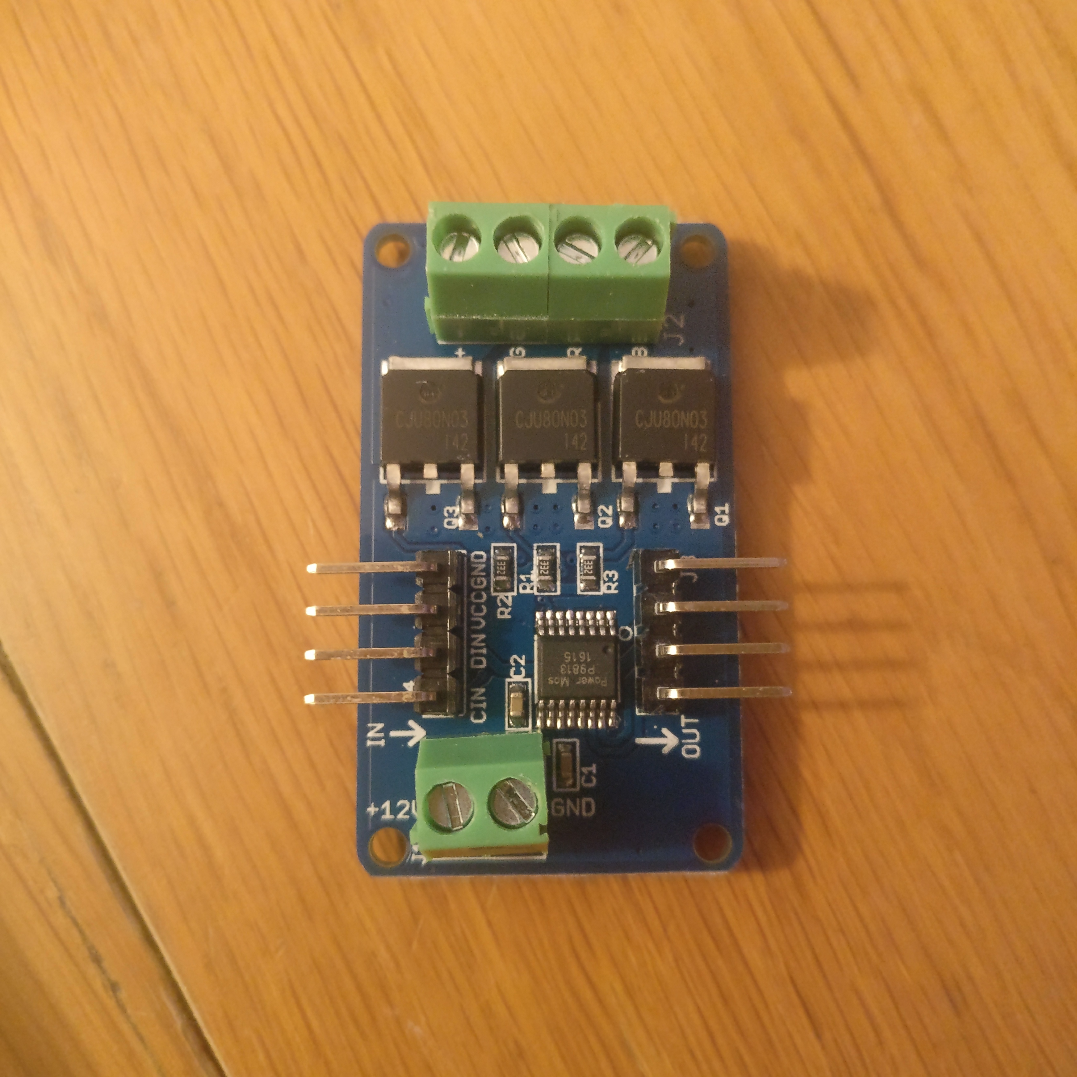
So I purchased a 2560 Mega and have the same issue I’m using a P9813 RGB controller and the shortest piece of code to test with. The Mega being powered over USB and the P9813 powered from a mains 12v adaptor.
Looks like there’s a + and - connection (along with Data and Clock) from the Mega to the strip controller board so that should mean everything has a common ground.
Two thoughts:
Not that I would think I would make any difference, but shouldn’t NUM_LEDS be 1 in this case? The whole strip would just be considered a single “pixel”, yes?
How many pixels does that strip have? I’m wondering if your 12V power supply is providing enough Amps?
Thanks for the quick replies. I believe the grounds are connected yes as Marc has said. Saying that though I can seemingly unplug and plugin the ground wire while the strip is on with no change in functionality, this is bugging me.
I have also tried running the Arduino from a wall socket rather than the USB port and no change there either.
I thought I had it when I realised the mega has hardware SPI on different pins, so I have switched to CLOCK_PIN 53, DATA_PIN 51 and its still the same
The strip is 5m with 300 LEDs, they are 5050 LEDs, the power supply is 5A. I have tried NUM_LEDS as 1 as well, no change.
Everything works perfectly at full brightness down to about 50% brightness, its when it start dimming very low that the flashing/pulsing starts.
@Kelvin_Mead I don’t have a higher amp supply to hand but I’ll dig through the parts box and see what I can find. I don’t understand why amps would be an issue if the strip works correctly at full brightness, I would assume that is using more amps than dimmed?
This is 12V power supply you are using, right? I’d suggest giving a different one a try (there are a lot of 12V power supplies, such as from older notebooks – if you don’t have any, go to a thrift store like Goodwill and dig their electronics section).
Another quick way to check the theory of power supply being the culprit is to test your circuit using 12V from your car (or car battery). Just open the hood and connect the terminals to the battery; no need to start the car.
Also, If you have a decent electrolytic capacitor (such as 15V (or more) 1000 uF (or more) – the more the better, something like 25Volts 4700uF will be great), try connecting it to 12V input (mind the polarity! or it will blow).
My theory is, power supply output is dirty, and its frequency collides with the P9813 frequency so you see this effect. Should be fixed by changing the PWM frequency – alas no way to do so with P9813, so change the power supply (or add a capacitor).
@Kirill_Kolyshkin nailed it, its the power supply! I don’t have anything to measure the supply but I switched to a PC PSU as a test and its working perfectly. So what is it about my 12v adaptor that isn’t good enough so I can find a replacement as the PC PSU isn’t a suitable solution long term.
@Simon_Hill1 it’s hard to say without being able to measure the noise. Given it’s affecting the LEDs when they are dim and not drawing a lot of power, you may need an LC filter. But it’s worth trying a few different values close to the power input of the module (accross the terminal). Do you have capacitors to try?
 I’m using a P9813 RGB controller and the shortest piece of code to test with. The Mega being powered over USB and the P9813 powered from a mains 12v adaptor.