Power Control of the K40 LPS

I think it’s how the laser is turned on.


I used the line that I mentioned. I have it starting on the upper left area of the machine and draws a line going to the right.

I move the head to the front right part of the machine.

As soon as I press the ‘start’ button, the pwm starts, even though the head has not reached the start area. The pwm is always present when a layer executes.


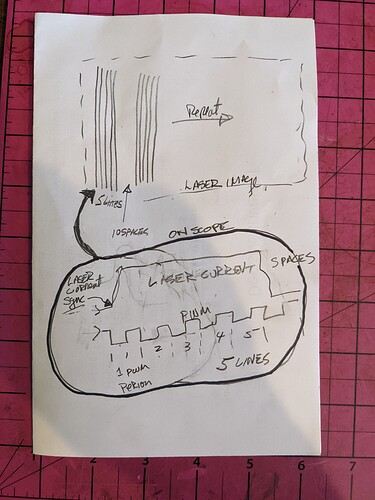
From the first image, you can see the pwm change, but the laser is responding to only the L-ON signal.

Don’t follow what you’re up to with the vertical lines…


:smiley_cat:

This is how the stock K40 and the Cohesion3D/Smoothie controllers are configured to operate.
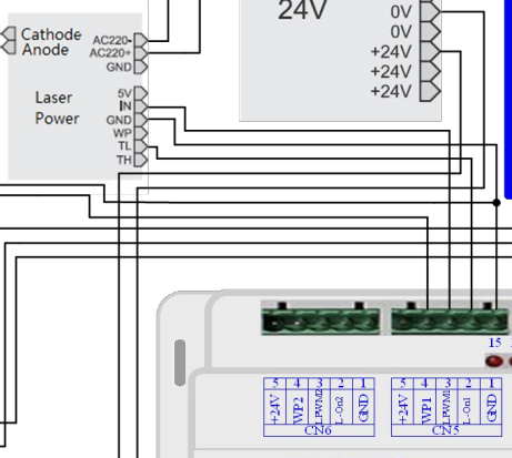
The PWM output of the controller is connected to the L signal while the IN signal is held via POT controlled voltage to the maximum current you want going through the laser tube.

I’ve heard of people trying to do control in the opposite way but I thought it was putting an analog input into IN and using L as enable(ON/OFF). Your posted pic shows you have it working using dithering( not grayscale/analog control ) which really means there’s just ON/OFF control needed since the color/depth of the burn is a function of how long the laser is on not how much power is run through the laser. Did I get that right?

The first image shows that the pwm width can change, which is what I’d expect from a gray scale image.

Many of the lps, that I’ve looked at will take an analog or digital input to the IN of the lps.


The Ruida manual has

Screenshot from 2022-05-21 14-12-02

:smiley_cat:

Here is the idea:

  • Create a pattern of 5 on and 10 off that repeats horizontally.
  • The scope sync is set on the laser current (might be unstable so adjust sync level)
  • Look at the PWM on second trace.
  • If the pattern repeats faithfully then you can sync on any combination of 5 without much jitter. OR use storage mode.
  • You can tell where the sync occurs because you can count the five periods of PWM.

Alternately make only one pattern of 5 that does not repeat and see if the above setup works better. The time between groups will be much longer however.

Try this also syncing on the PWM. Again you can tell where you are by looking at the groupings.

My basic understanding of lasers tells me they are on or off. When it lases it will draw as much current as the lps will supply.

There is no 50% power on a laser, I.E. it’s 100% power for 50% of the time. You’re only real control is speed.


Main reasoning behind setting the ‘lps’ to a known current limit for tube protection.

I checked my new machines current draw to be 14mA at 50% power. I read that as 28mA being available at 100% power.

My tube maximum is 21mA (50 watt 880mm, 60 watt supply).

When the tube lases for even an instant, it can draw 28mA, too much for my tube. I turned it down to 10.5mA at 50% power. At 100% it can’t draw over 21mA… So when it lases, it can only get 21mA from the lps.

It does draw 21mA @ 100% power… when commanded.

If I’m wrong here, please clarify… as I’m not following you thoughts…


@donkjr When I have a few I will inspect your details and see if I can follow what you suggest…

From what I can figure, you’re going on I’m triggering at the wrong time and missing what I think I should see?

Kind of an obfuscate statement, hope it makes sense…

Thanks to both of you for your time and patience…

:smiley_cat:

The main power control from the working program is PWM. The DF of the PWM determines how long the laser is on over the PWM period.

Power =
50% full on for 1/2 the cycle
75% full on for 3/4 of the cycle
100% full on for the entire time of the cycle

Using IN for PWM and L for enable:
In your setup with the PWM controlling IN the max power is only controlled by the PWM value. The L signal enables firing.
I do not like this approach because the only max control is the programmed PWM. This means that as the laser wears you have to adjust each program vs just adjusting a pot.

Note: the total power in these supplies = L [df] * IN [df]

This is wired up as specified by the controller manufacturer, Ruida.

I have had mine a year and there hasn’t been a change in the values. I’m aware of the probability, but haven’t seen it yet and I watch this rather closely. I’m sure it will happen, but it’s been very consistent up to now anyway.


I think it’s one of the things that make reading the K40 stuff interesting as to how they handle the same thing differently. Never had one, but they are an addiction… Trying to figure out how to afford a fiber laser… need to come up with about $4700 bucks… so far it’s just a dream.

:smiley_cat:

1 Like

I even zoomed into Russ Sadler’s 2nd video on installing a Ruida into a K40 and sure enough there was the PWM labeled output on the Ruida wired to the IN on the LPS and Ruida L-ON wired to the L on the LPS.

So I’m wondering what is in the IN circuit of the LPS which results in the proportional voltage of the PWM input.

The IN is an analog input that controls a PWM IC that drives a high voltage H switch. Yah, it’s not that simple but good enough to understand how to use the LPS optimally.

You can control IN with an analog value but a PWM would also work (its two analog values 0-5v).

That is why when the IN is set with a DC value and the L input is a PWM signal the net result is a “PWM of a PWM”. You get external offset control and the programmed PWM does not have to change as the tube deteriorates.

You can also turn the L on and off. However, you cannot externally [to the controller] set power this way.

And there are ways to disable the LPS via other inputs if you want to other than L.

Remember that these are the same vintage folks that think a digital panel (which by the way is a PWM on IN) somehow improves tube control. And to help conceal the problem take away the one thing that tells you what the tube is really doing… the analog meter. In reality, it gives users a false sense of control, and tubes are prematurely worn out.
Showing a percentage of power (which is actually the IN PWM’s %DF) is by itself misleading unless you know the tube’s actual PWM vs Current characteristic curve.

These are also the type vendors that tell you that the IN and L is a TTL control…

After all, they do sell K40’s tubes and LPS.


When you have one input (IN) that has analog control of PWM and another with ON-OFF control why would you not control IN with an external pot and the other with a programmed PWM.

One reason may be that this supply was originally put in a machine that had no power control and was imaged by dithering???

We have measured tubes over time and the IN vs tube current curve does change necessitating an “Intensity control”.

It’s my view that these vendors do not care that users may have to constantly change the programmed PWM to get the best results and they do not care if tube life is shortened.

They also do not want the expense and the costs associated with wiring a pot and meter. After all, a digital panel is more “cool” and digital is always more accurate … heh heh.

Most also do not know what is on the inside of that “blue box” so they do not know any better.

2 Likes

It does seem that as a maker group, we could redirect users to change their Ruida wiring for a better long-term experience by swapping the PWM to the L signal and installing a POT on IN?

Maybe Jack is up for showing the results of such a change?

I do like having my little tiny volt meter display on my IN signal and the milli ampere meter showing that state/health of my tube.

1 Like

I think the Ruida is a commercial grade controller, meant for production equipment run by the typical employee with no technical knowledge. Having the operator manually adjust anything is usually avoided by companies. They hire technical people that set the stuff up and maintain it.

In effect the machine needs to have a PHD (Push Here Dummy) for consistent production runs.

Most of the stuff you speak about, well you are far too knowledgeable, and it seems they can’t get people smart enough to ‘flip burgers’ at $20/hr… :crazy_face:


@donkjr I essence am I not doing what you are doing.? I think, set the pwm control to it’s max tube current state. Yours is on the panel and mine is a pain in the a** to get at.?

Is this adjustment done for every job on the K40.?

No ‘hands on’ with a K40, so forgive my ignorance.


@dougl I wish you hadn’t brought up the ‘mod’ to see what happens… first thought was naw, not going to change the factory setup, but I might give it a shot…

I’ve got the breadboard on the laser now with a photo transistor. I’d like to know how fast I get ‘light’…

Take care… thanks

:smiley_cat:

No, think of it as an “intensity” control. You adjust it a bit at a time, dependent on how much and hard you use the tube. It’s also useful when you want to experiment with new jobs especially engraving.

I’m sure you’re right. I have been staring at this LPS for a long time, way back when K40s started to be popular. From the start, the LPS technical literature has been lean and wrong to misleading and has for the most part stayed that way. That is why I dove into its guts.

I think that controller manufacturers like Ruidia do not know any better and it does work so they just stay with what works. They just believe the labels on the interface. I don’t think they make the LPS.

There is no harm in interfacing to the LPS using IN but it is IMO not the optimum setup. To me, the most pressing omission is the laser current meter.

@dougl we have been preaching this LPS setup to makers for a long time.

Moving on…

1 Like

Working on a few things… will report back with the photo transistor experiment.

Probably start a new thread. I’m going to drop a note to Russ and see if he can suggest what’s going on. He knows both of these machines pretty well…

Thanks to both of you, take care.

:smiley_cat:

I’m going to see what Russ thinks about doing the IN / L swap on his Ruida’s and make a video.

Let’s not hit him with the same question at the same time…

I think I need to look at how the K40 is wired and how the pwm is used. Does the K40 produce a pwm anytime you are executing a layer?

Second, the IN input is active high and the L input is active low… so a change somewhere else needs to take place for it to work properly. I think you can invert the L-ON output…

:smiley_cat:

oh, I didn’t know you were in comms with Russ and had considered asking him about this. Ya, no need for a hit from two sides.

Yes, it’s going to set the power level via PWM per pixel during the burning process.

Good point and no doubt Ruida has a setup entry for that but I can’t say where it is because I don’t have any Ruida machines I can poke at.

The question was does the pwm run even if the machine is only moving to the next spot to lase?

On my little machine (led laser) the pwm is only active when it’s burning, not so with the Ruida.

:smiley_cat:

The standard way the K40(analog version) works is:

  1. The POT across 5V/IN/Gnd sets the max power output of the LPS with a DC voltage. That is fixed and is set when the machine turns on.
  2. The controller puts out PWM into the LPS-L signal control which set the laser on/off at defined power levels based on the PWM.

So ya, the PWM stops when the firmware is told to not lase anything. It’s a one wire control.

I don’t get why Ruida would be outputting any PWM values when the laser is not supposed to be doing anything or what PWM value they would think was valid when the laser is not supposed to be powered. The Ruida does use the L-ON signal it seems to enable and disable the laser so I would expect that signal could be used with one of the safety signals to disable the laser during moves and non-firing modes.

It uses whatever value you enter for that layer and is present for the entire layer, even if it’s only lasing in a few places. When it moves to the next layer that value is present on the pwm output.
It’s running the layer, so it may not matter if it runs all the time.

I think I get how it’s working, just can’t see what I think I should on the scope.

:smiley_cat:

I think I get what you are saying. When cutting and dithering the power level is fixed by setting for the layer and what Ruida does is spit out that PWM constantly even when it’s not putting down dots, lines, etc. It uses the L signal to turn on/off the laser in concert with the PWM pulse when time to put down marks and/or cut.

I was thinking about grayscale again and that’s when the PWM is changing all over the place based on the power level set by the gray scale.

You might want to zoom in on the L signal and see if there isn’t far more ON/OFF levels than what it looks like from the view previously posted(time domain).