The above is why I suggested you try syncing on the laser current and looking at the PWM.
The L-on may be an enable at the start of the job, line, or who knows what. The start of firing may or may not be the L-on? So you may see traces where the PWM and L-on are out of sync. It depends on when the scope happens to trigger amongst a gaggle of scans.
In an original* K40 and controller, the image is dithered and therefore the beam is turned on and off with the L signal for each pixel position. There is no grey shade. [this is what I was told].
Stock controller with in-the-box software.
Smoothie controllers only turn on the PWM signal when needed [which is a composite of L-on and PWM] this is why an additional “enable” is not needed and the IN can be used as a power adjustment.
Keep in mind that aside from how it is used IN is really an analog input and L is expecting a solid ground. Neither circuits are actually a digital signal in the classic sense.
Oh, and BTW if in a Rudia machine the PWM and L-on are synced changing it to a pot and L may not work.
During my ‘sleep thinking’ last night I hit upon the idea of logically ANDing the two Ruidia output controls to get a functioning output for LPS-IN control.
I am in the process of designing a small controller based on an ESP32 board to control (via FluidNC) an old trotec laser refurbished with a chineese 40W CO2 laser + lps. (I will trash all the electonics inside the trotec, keep only the mechanical parts + switches and DC motors that I convert to “pseudo steppers”).
And finally I wonder if my idea to PWM the IN signal is the right approach !
If you convince me that PWM on L is the best approach then it will be simpler for my ESP32 as I can directly input PWM at 3.3V on L pin and the opto on the D/L pin will do the level shifting to 5V for me !
BTW is the opto fast enough to handle PWM frequency ? How fast should it be to properly modulate the laser power to engrave images ?
Thanks for your help : this forum and this thread are particularly interesting !
There are lots of “opinions” on this subject. As always there are tradeoffs to each of these methods.
I have run my K40 for years with PWM on L and a pot on “IN”. I have also assisted countless others with this same setup.
I think the ability to set the max power outside the driving program is a benefit since the laser’s power diminishes over time. I did not want to have to tweak the program as the laser wore out.
Yes. The L input on the LPS is also an optocoupler.
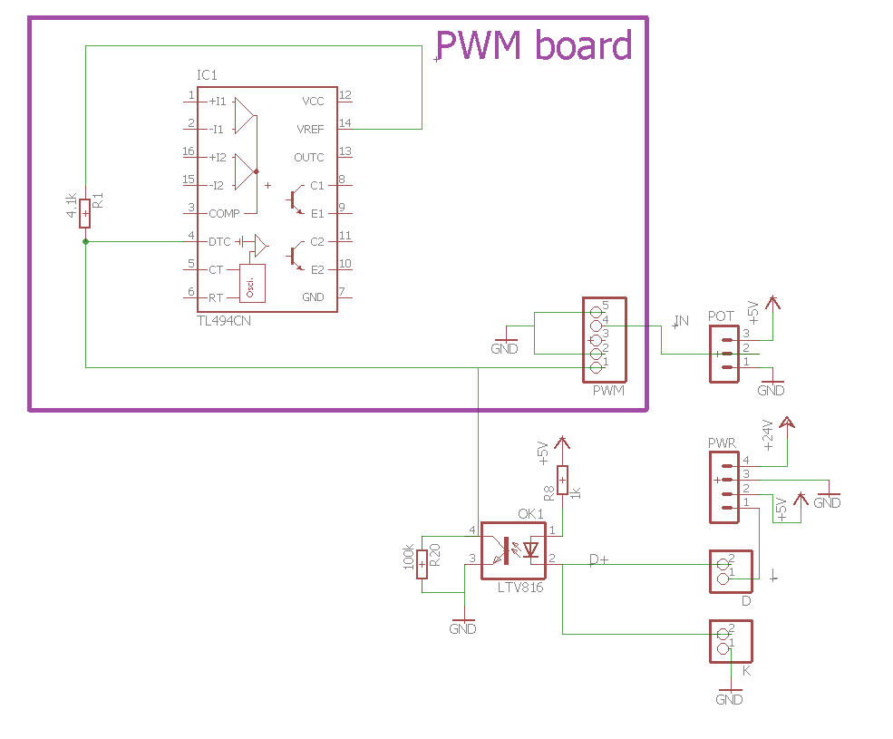
I got a schematics from @Paul_de_Groot (thanks for this if you read me !)
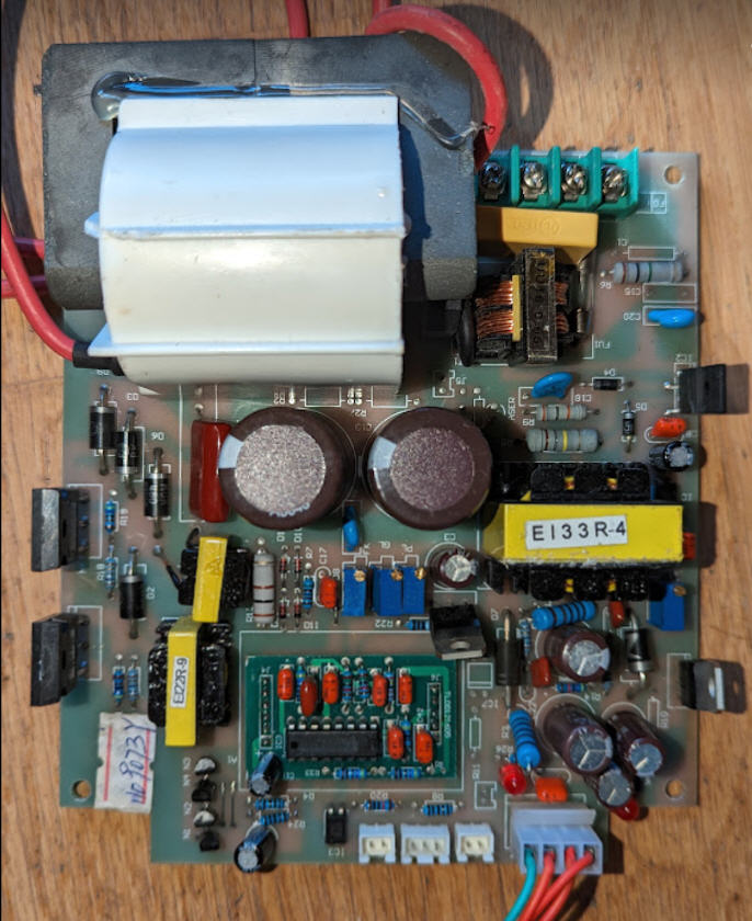
But the “input part” of my LPS didn’t follow this schematics.
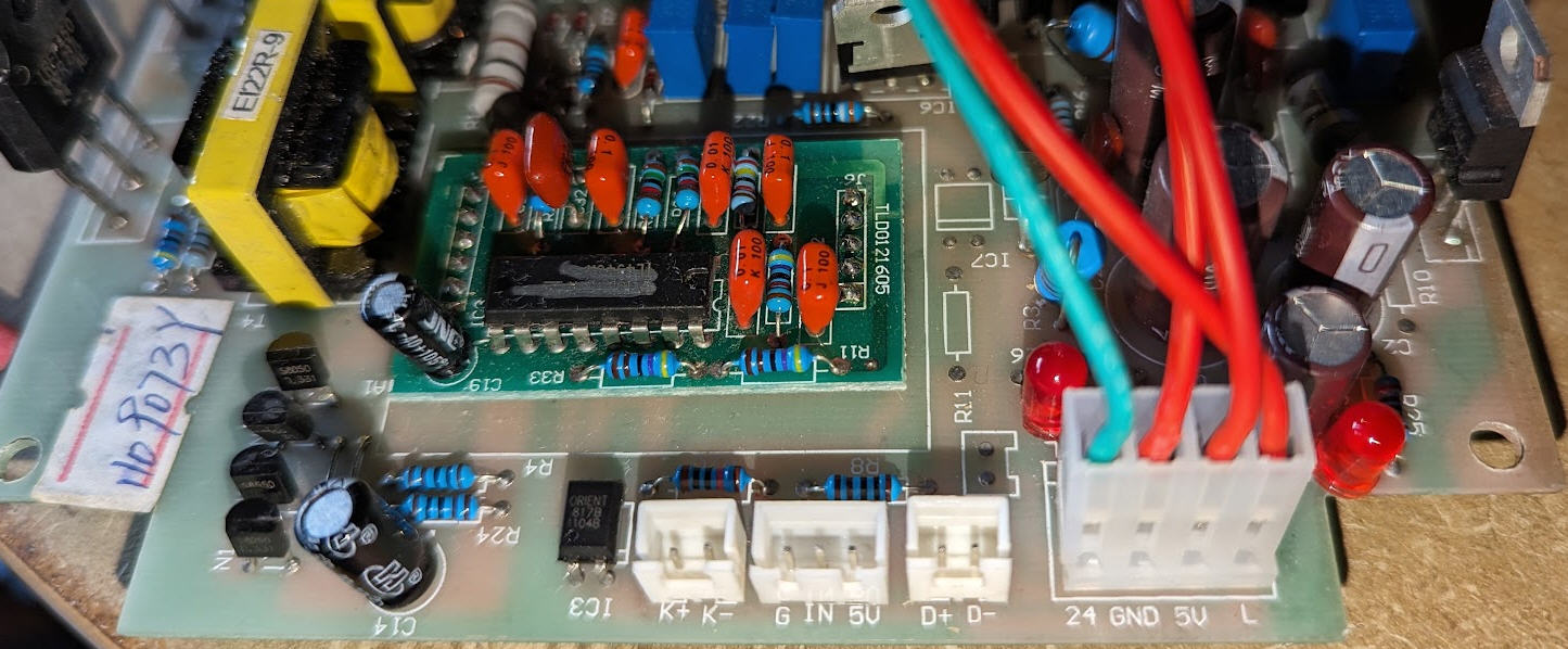
So here is what I found when tracing my PCB.
What was surprising for me is how the optocoupler was wired with resistor R20 to ground… This wasn’t classical at all !
So I traced a bit more and went to the TL494CN chip.
And here is my interpretation:
R1/R20 is a voltage divider between VREF (5V) and ground
this voltage divider is applied to pin DTC (dead Time Control) of the PWM chip
when opto is off (L pin or K pin or D pin not grounded) then the phototransistor is not passing and the voltage divider is applying R20/(R1+R20)*5V = 4.8V to DTC pin
When opto is grounded then its phototransistor is passing pulling pin4 to (almost) ground. Thus the output of the voltage divider is now 0V (almost)
If we look at the datasheet we can read: 9.3.3 Dead-time Control The dead-time control input provides control of the minimum dead time (off time). The output of the comparator inhibits switching transistors Q1 and Q2 when the voltage at the input is greater than the ramp voltage of the oscillator. An internal offset of 110 mV ensures a minimum dead time of ∼3% with the dead-time control input grounded. Applying a voltage to the dead-time control input can impose additional dead time. This provides a linear control of the dead time from its minimum of 3% to 100% as the input voltage is varied from 0 V to 3.3 V, respectively. With full-range control, the output can be controlled from external sources without disrupting the error amplifiers. The dead-time control input is a relatively high-impedance input (II < 10 μA) and should be used where additional control of the output duty cycle is required. However, for proper control, the input must be terminated. An open circuit is an undefined condition.
So that, this DTC pin is indeed used to control the output of the PWM. When K or L or D is not grounded DTC pin is at 4.8V → full dead time… power off. When K or D or L are at 0V then DTC pin is at its lowest value (110mV) → minmal dead time. The laser is totally On. The LPS is regulated by the other comparators (IN input)
So IMHO the usage of L pin to control the laser power is totally valid.
Applying a PWM signal on this pin is not a hack but follows precisely what is intended by the datasheet:
With full-range control, the output can be controlled from external sources without disrupting the error amplifiers.
The dead-time control input is a relatively high-impedance input (II < 10 μA) and should be used where additional control of the output duty cycle is required**
This L pin PWM can be “digital” or could even be “analog”. Thus we do really have 2 PWM inputs on this LPS : the IN one and the L one. (Don was right!)