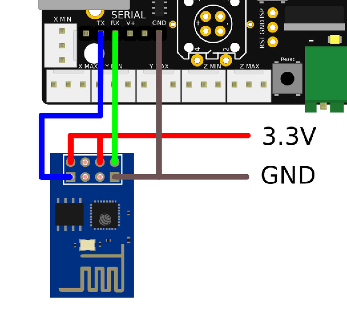
+Peter van der Walt is this how you would recommend connecting the ESP to the smoothie? I’ve been working on fleshing out the wiki page for this and would like to add this illustration, but wanted to check with you to make sure the connection is correct. I unfortunately don’t have a smoothie, but a MKS Sbase. It’s working ok, but I can’t get it to talk to the ESP, so I can’t verify the connection.
I’ve branched the wiki, but being new to GitHub as a contributor, I don’t know how to push my changes to the master fork.
Yeah, what +Peter van der Walt said we pretty much put a 10k resistor anywhere we could :).
Either of us can pull up schematics from the ESP12 on our boards if you need help just ask.
I would agree. I’m actually a bigger fan of the NodeMCU, but they’re all similar enough.
My understanding is that the ESP01 is the ESP12 for people who don’t want to solder it/ deal with that particular placement type. Essentially it’s the pluggable equivalent. But it would still be into an application that is prepared to receive it with those other components we discussed.
Thanks for the kind words +Peter van der Walt! @donkjr sorry for the delayed response. I’m using Inkscape. I try to find images I can pilfer from the web and then “sew” them together. Do you need an illustration done? I’ll do what I can to help. My turnaround time isn’t necessarily too fast (work, kids, an old run-down home, etc.) But it offers a good distraction! I’m just starting to draw a schematic for my Laser Safety installation based on @funinthefalls 's system. He was looking for a schematic some time back and I’ve finally got my system up and prototyped this weekend.
Looks very interesting @donkjr ! I might be able to help. As you saw above, I found a nice svg image of the smoothie. I can look for other images of the other parts too, and draw some if I have to and then link them together. Let me know what you need.
 …
…