I am doing quite a lot of heavy modifications to my PC case, and I am stuck on an issue involving a Capacitive Anti-Vandal Momentary switch (CS4M2FR information) as I have next to no electronic experience. I want to wire the switch in parallel to the current switch so that I can use it as an alternative switch located on the top of the case which is an easier to reach location then behind the lockable front panel door.
Through trial and error I have worked out I need to connect the ground (Black) to the negative pin for the power switch, the NPN (Brown) to the positive pin for the power switch and the 5-24VDC to the positive pin for the reset switch. On page 4 linked here of the switch data sheet. It details an example use case that is directly applicable to what I require however my limited electrical knowledge means I can’t decipher it.
.
If I ground one of the colour led wires against a metal panel then that corresponding led lights up constantly regardless of whether the switch is in an off or on state. If I connect a colour led wire to the negative pin for the power LED then it lights when the system is off and turns off when the system is on (the reverse of what I want).
As I understand the switches interface:
Pin 6: power 5-24V
Pin 5: switches when the button is pushed and grounds pin 5 [turning on load]
Pin 4: when grounded turns on Red led
Pin 3: when grounded turns on Green led
Pin 3: when grounded turns on Blue led
Pin 1: connect to ground [other side of power on pin 6
The application instructions are a bit vague but I assume this switch is intended to:
Switch a load on pin 5 when the button is pushed.
A processor watches pin 5’s state and then turns on one or more of the led’s by grounding their associated pins.
If I ground one of the colour led wires against a metal panel then that corresponding led lights up constantly regardless of whether the switch is in an off or on state. [I would expect it to work this way assuming Pin 1 connected to the metal panel and the - side of the power supply is connected to the metal panel]
If I connect a colour led wire to the negative pin for the power LED then it lights when the system is off and turns off when the system is on (the reverse of what I want). [by power LED do you mean the CS4F2MR? What is pin 1 connected to in this situation]
What is JFP1 above? Is it the PC’s connector?
Is there a reason you are using the CS4FMR vs just a simple switch?
Can you provide a drawing of
How you have the switch wired for the above tests
What you want the switch wired to and the functions of those connections
How you would like the switch to function?
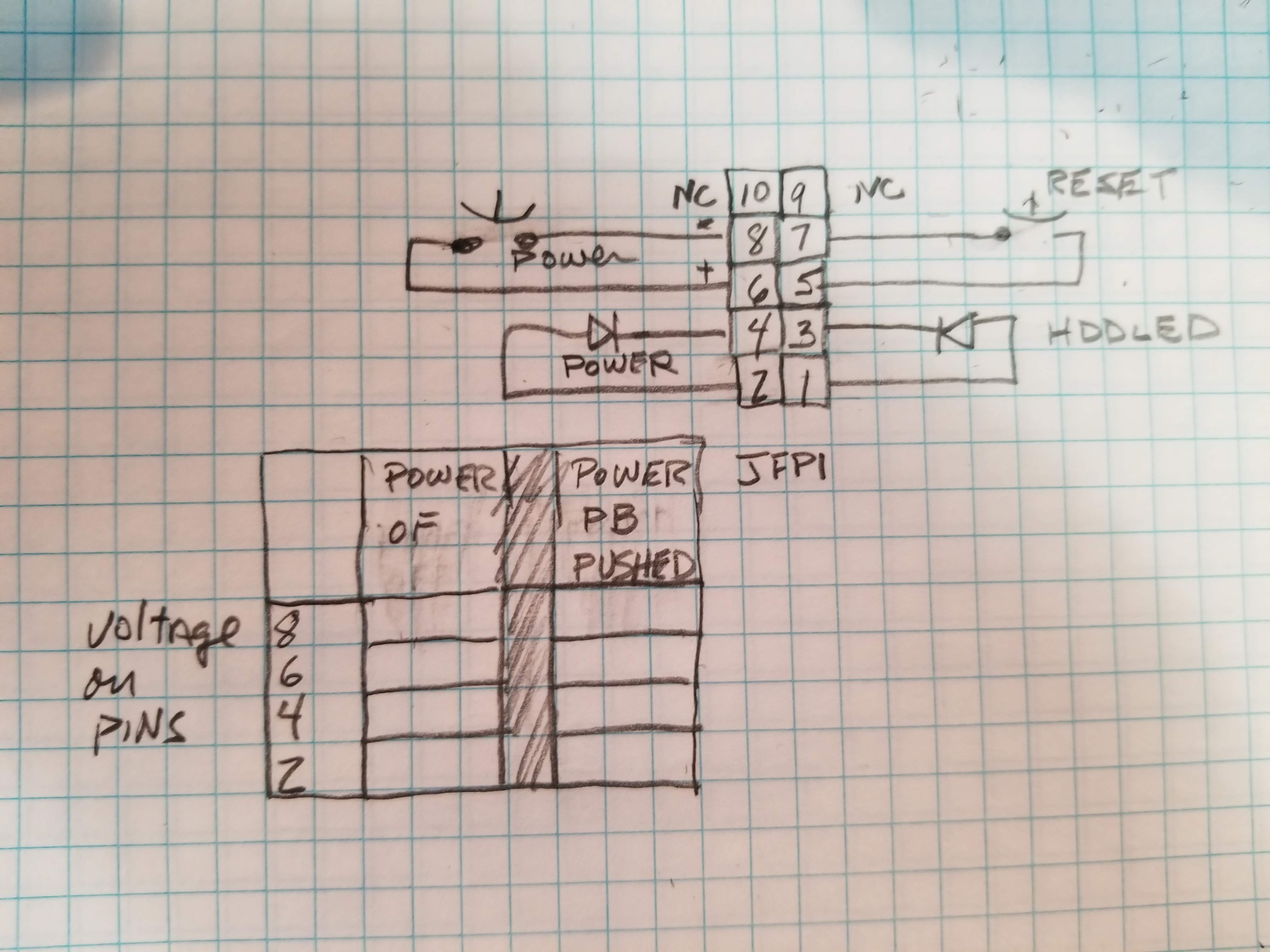
The below drawing is how I would to guess how to hook it up to JFP1.
However not knowing what is on JFP1 you could damage the PC inputs/outputs if I did not guess right.
Use at your own risk …
I would first test JFP1 to see how it operates without the new switch installed.
Is pin 6 a constant DC voltage? What voltage?
Does pin 8 go to ground when the current power button is pushed?
Does pin 4 go to ground when the current power led come on?
Thank you for your help so far I think I follow your logic and it is definitely helping me understand how the switch functions. Hopefully I can answer your questions where possible with my limited understanding.
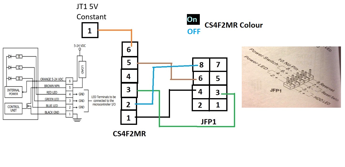
A desktop PC use a momentary anti-vandal switch for the power on button to tell the PSU to power up and initiate supplying power. A supposedly simple mod is to introduce your own momentary switch and wire it in parallel to allow for 2 switches and therefore 2 points to turn on the PC. Normally someone would use a simple switch like this to achieve that. But I decided to be too clever for my own boots as I wanted it to change colour based on the power off or on state of the PC. Ideally I want the switch to light up White when the PC is on and Blue when the PC is off. To use the schematic of JFP1 pin headers above again. I want the momentary switch to connect JFP1 pins 6 and 8 at all times and when pressed initiate a change in power state (turn off/on the pc). I want all LEDs to light (to create white light) when JFP1 pin 2 is active. Then with the Blue LED remaining on when JFP1 pin 2 is turned off. On page 34 of my motherboard manual is the specific pin map which matches the JFP1 connector as shown above. JFP1 uses 5 volts on each positive pin and only pins 6 and 7 have constant power with pin 2 live when the PC is on.
By power LED I am referring to the CS4F2MR lighting up and in this situation it is the Green LED. In this configuration when JFP1 Pin 2 is live no LEDs are on and when Pin 2 is off then the Green LED on the CS4F2MR is turned on.
How do I test this? If Pins 6 and 8 are shorted then the PC changes power state from off to on or vice versa. Leading me to believe pin 8 is always grounded.
Unsure how to test this, but if I connect the switch to JFP1 pins 4 and 6 then the switch turns off and on the PC leading me to believe pin 4 is constantly grounded.
Between JFP1 pins 6 and 8 is a momentary switch for power it doesn’t latch in a set position as shown to complete the circuit it just makes a connection whilst the switch is active.
The current button doesn’t have a spec sheet as it comes with the computer case it isn’t intended as a customizable part. This is a replacement part that is very similar to the current one installed.
Beyond the user manual no I do not have schematics for the motherboard. I was thinking of using the JRAINBOW on page 41 of the manual to see if the 5V pin or Ground pin are disconnected when the PC is turned off and reconnected when the PC is turned on. Tested with connecting pin 6 from JFP1 to pin 4 (Ground) of the JRAINBOW1 and the switch turned off and on the pc leading me to believer JRAINBOW1 has constant ground.
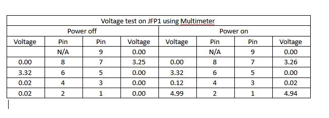
Measurements taken with negative side of multimeter attached to the PC case frame as ground and the positive side used to measure. Did you want me to measure with the momentary switch on pins 6 and 8 held down?
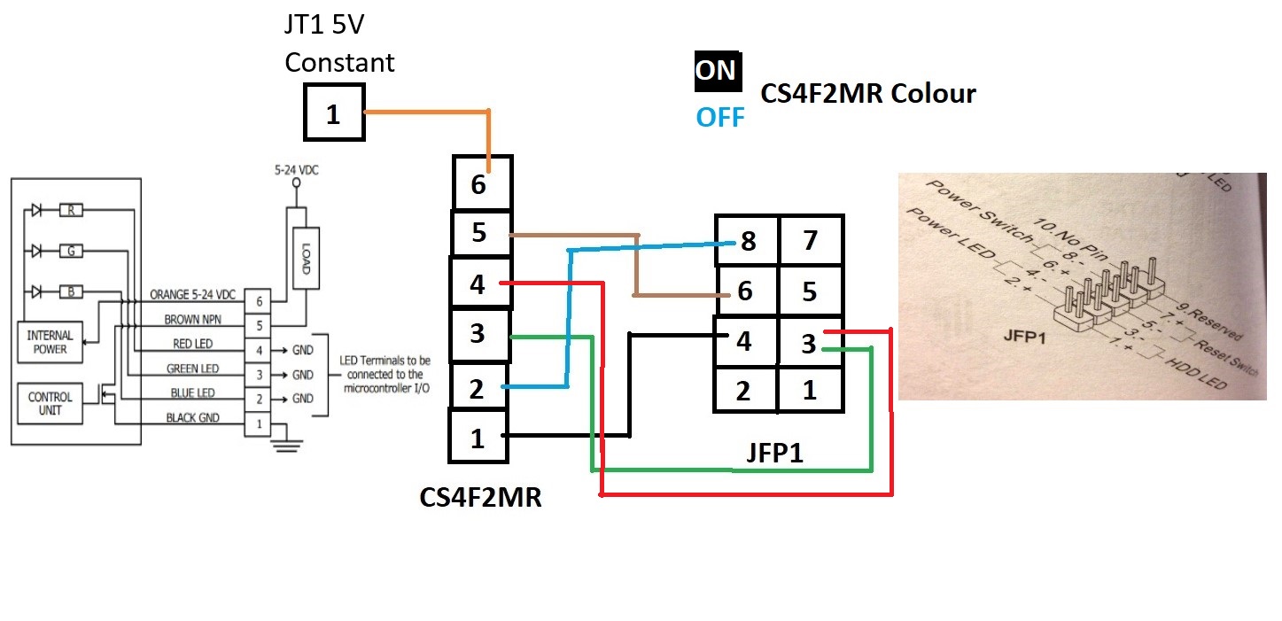
Thank you, Don for the probing questions and help by drawing out the pin maps and circuits logically. I am so close now but it is still not 100% right. The image below result is the result of some trial and error. I realized the Orange wire (6) from the CS4F2MR needed a constant positive of at least 5V to function. So I checked all available pins on the board and found JT1 (not listed in the manual) gave 5V when the PC was both on or off. The NPN Brown wire (5) was the switching part of the connection and the Black wire (1) needed constant ground to allow the switch to function as expected switching the PC power on and off. I then tried connecting it up as below:
When the PC is off the CS4F2MR is a bright blue colour and when the PC is on the CS4F2MR is a bright teal colour (Green and Blue combined lacking Red).
I am now stuck trying to figure out the correct placement for the connection of the red LED wire. If I connect the red LED to ground on any point I get purple on the CS4F2MR when the PC is off and white when the PC is on.
 .
.