Originally shared by Nicholas Seward
I think I cracked this problem wide open.
n_sun=30
n_planet=14
n_ring_blue=57
n_ring_green=60
Mechanical advantage:
57:1 sun->ring_blue
58:1 sun->ring_green
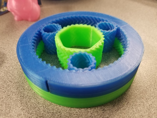
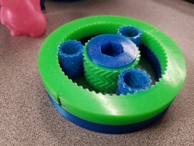
Planets are printed with 3 perimeters so they can flex. They ended up way stiffer than I expected but it ended up being right for the design. You can see that they oval out just a bit from the pictures. The sun gear is also designed to flex for assembly but then accept a core as shown that makes it rigid and allows you to drive it from a pulley eventually. I got a quote for nylon SLS versions of the planets and they are less than $5 but for now PLA seems to do the job.
With the addition of the largest pulley size that won’t extend beyond the joint, you can up the mechanical advantage by a factor of 7. That makes the end mechanical advantage anywhere from 57 to about 400. If required, the planetary harmonic stage can be tweaked to get the total mechanical advantage all the way past 1000:1. I don’t need anything that crazy but it is nice to know that I can reach ratios from 50 to 1000 with relative small changes within the same sized joint.
I haven’t measure play in any scientific way but it is pretty much non-existent. I generated an arc-minute move and verified that I could detect it with my eye. I then applied alternating torque with hands and couldn’t see any movement much less an arc-minute shift. My calculations put that at less than a .1mm error at the end of a 300mm arm. It is also important to note that this was after I broke it in by draining all my cordless drill batteries. I would say I ran the joint for 30mins at 60rpm. There was a small amount of surface polishing on the gear surfaces but I feel that we can reach at least a million cycles with no degraded performance. Cycles to failure should be much beyond that.
I tried to fight the torque with my hand and it was impossible. I also applied force in all sorts of directions between the two ring gears and any movement could easy be attributed to the sun flexing and the movement was super small at that. I wouldn’t scoff at using this reduction on a light weight joint without a bearing. There are also a ton of ways you can make this even more robust to handle high torque applications without a bearing.
Everything is designed to eventually fit inside the 6814 bearing inner diameter of 70mm. Overall the design is 20mm thick which seems to be more than I will need but going thicker is an easy way to reduce play, increase allowable torque, and possibly increase the number of cycles to failure.
The sun and planets use a legit cycloidal gear profile. https://docs.switzernet.com/people/emin-gabrielyan/100512-gear-engine/ The ring gears are generated algorithmically using what I can virtual gear hobbing. The pitch diameter for the ring gears is for 58 teeth but to allow for harmonic goodness…one actually has 57 and the other has 60 teeth. Since, these deviate from the mathematical perfection of the cycloidal profile, they have to be generated by running the planet around the ring at different speeds to see what gets cut away.
I know some people will have questions about the choice of gear profile. Involute profiles require a bit of sliding between mating surfaces and the rolling friction increases as the forces between the gears increase. Cycloidal profiles in theory have pure rolling motion. In theory, the rolling friction is much more independent of the inter-gear forces. If you look at the link above you will see that it is possible for cycloidal gears to loss contact. This is where the herringbone design comes in.
I don’t know if I will build a actuated test rig or just go ahead and integrate it right into a project. I feel very confident in its performance and it would be great fun to build a robot arm.


