I recently upgraded to a MonPort board to be able to use Lightburn, this worked ok, but rendered the original digital power panel inoperative. To aid with setting and visualisation, i went about an Ammeter installation using https://www.amazon.co.uk/dp/B071S1D414psc=1&ref=ppx_yo2ov_dt_b_product_details
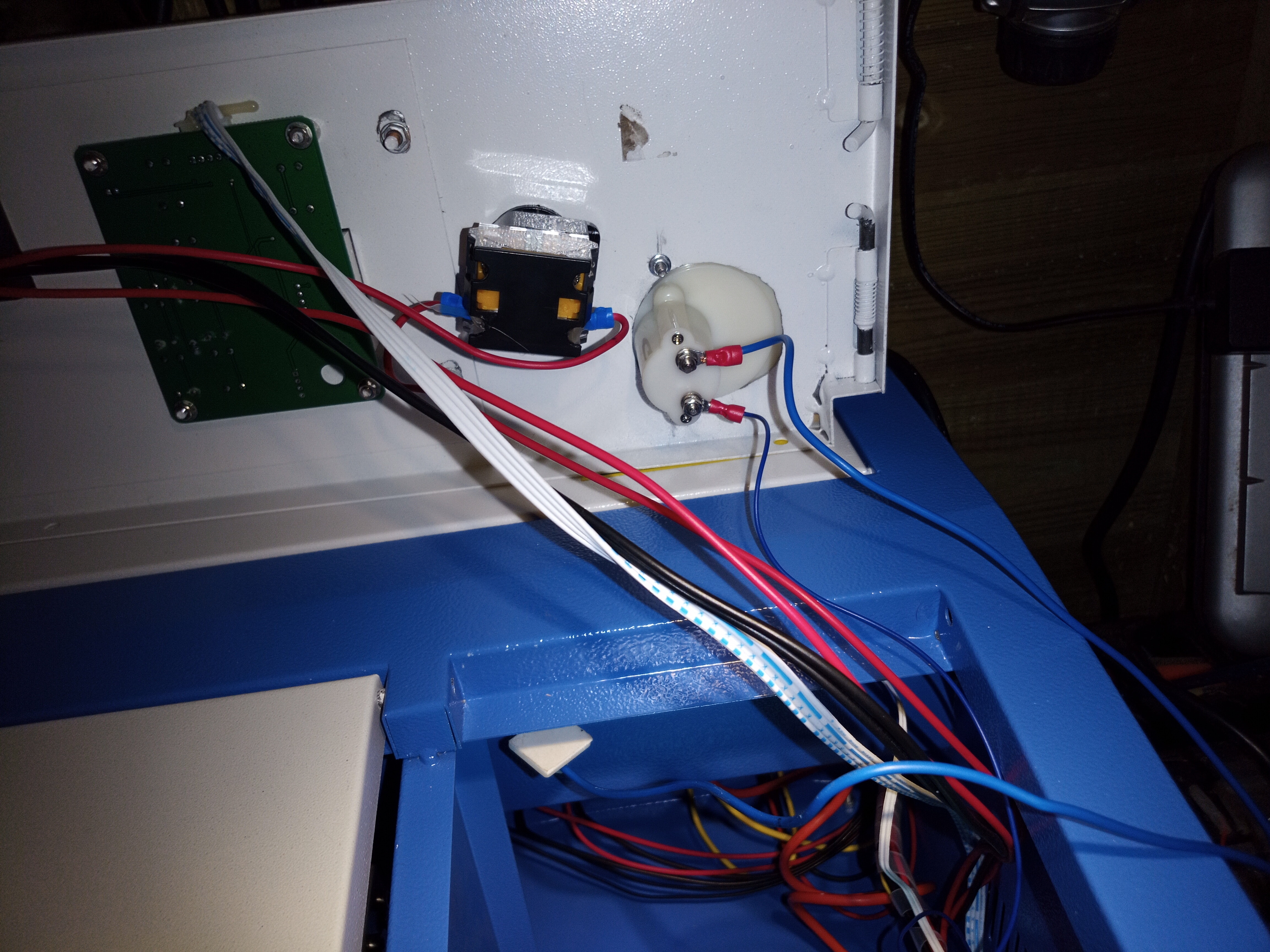
and connected it inline with the Blue cable from the tube to the right connector and a Blue cable from the left to the existing connection ( looking from the back).
I managed to trip the mains before realising i had messed up the power switch connections and rectified this. With nothing tripping now, i still have no power at the PSU ( Internal fuse appears intact). Re-checked the cabling and rectified an issue with the 24v/5v output connector being misaligned (missed the first pin on the left so everything was one over) I dont know if this may be related, i am unsure tbh.
The only connections that have been tampered with are the mains switch, emergency stop and the tube common. I have checked for foreign objects getting into the PSU although it was covered, but cannot see anything.
I do not see an LED on the PSU or Power switch.
Can anyone advise the best steps to follow to check the cabling over again ?
Has the tripping caused an issue i am neglecting to take into consideration ?
Any help gratefully recieved, and i am happy to try anything and provide feedback as to results. However, please be patient as i am recovering from a stroke and may not complete tests as quickly as normal.
And a bit scarily, as I was reading the description of installing the mA meter I pictured the tube being bypassed and the direct output of the HVPS going to the mA meter then to HL/return. Seems the mA meter was put inline on the low side of the HV circuit so a-OK depending on how good the connection is.
The monport board is a GRBL replacement designed for LightBurn and works ok, but the wiring required the digital panel to be disconnected rather than bypassed Pre Ammeter it ‘appeared’ to work as expected but could not see what power was being sent to the tube.(Upgarde K40 Laser For LightBurn | Nano Control Board — Monportlaser)
They provide a cable to make the connection from controller to psu, so not something i have fitted myself.
I am in the UK and unfortunately the laser is in my shed so cannot get a decent picture until tomorrow, but basically removed the blue cable from the leftmost pinout on the power connector and attached to the right hand side of the ammeter ( looking from the back) and added a new cable from the left side of the ammeter to the leftmost pinout. I have re-wrapped cables with the plastic tubing, would you require this removing again for a picture? The original cable was longer and i looped it puttting it in the tubing, didnt think would cause an issue but worth mentioning for clarity.
The Blue cable from the tube appears to have been spliced onto the original, which i believe was yellow. However i have looked at it so many times i need to go back and check this to make sure i am not mistaken. If it has been spliced, would i be better soldering heatshrinking for safety ?
new blue cable slighter thinner but can change if you think it will cause issues.
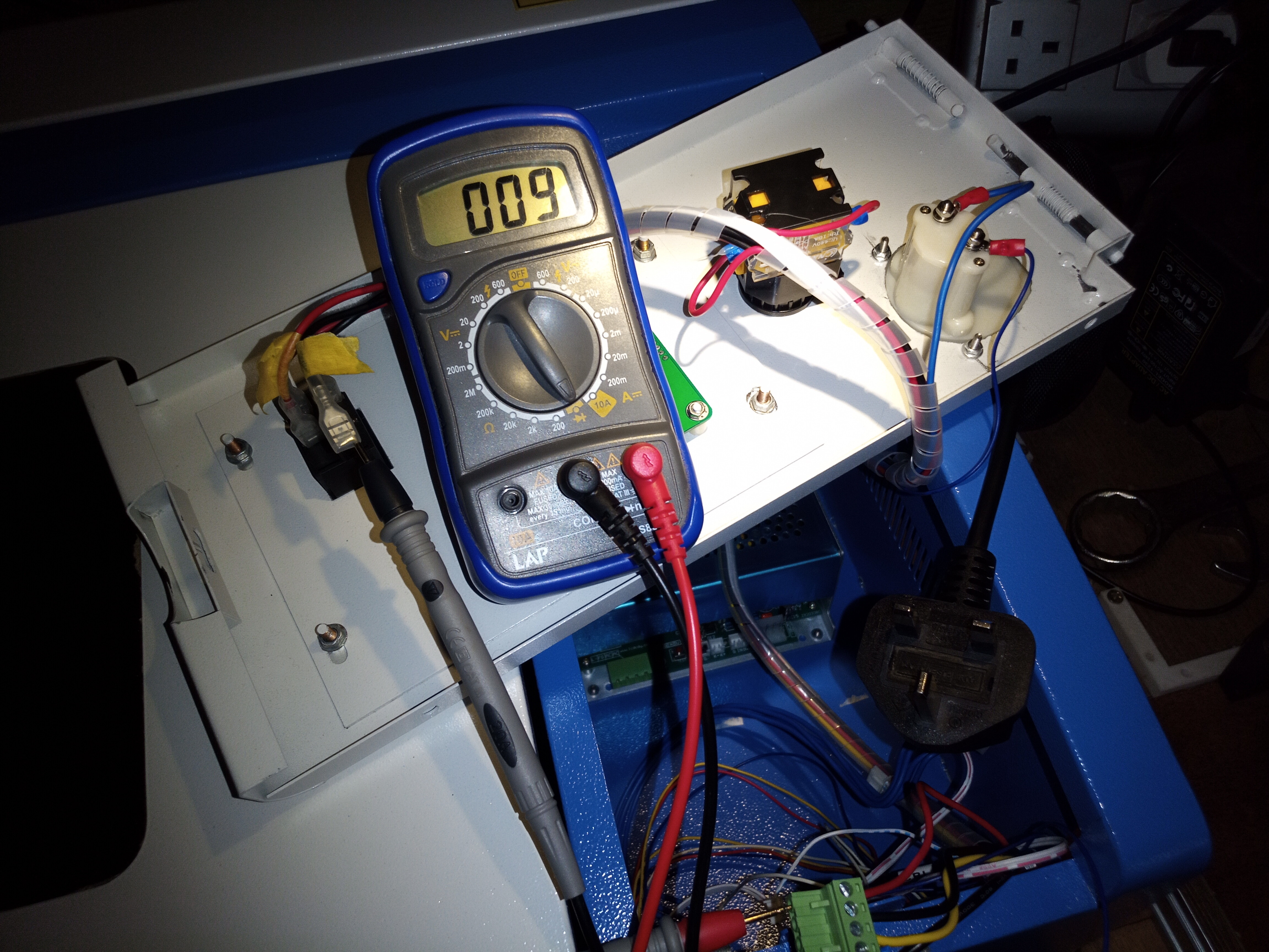
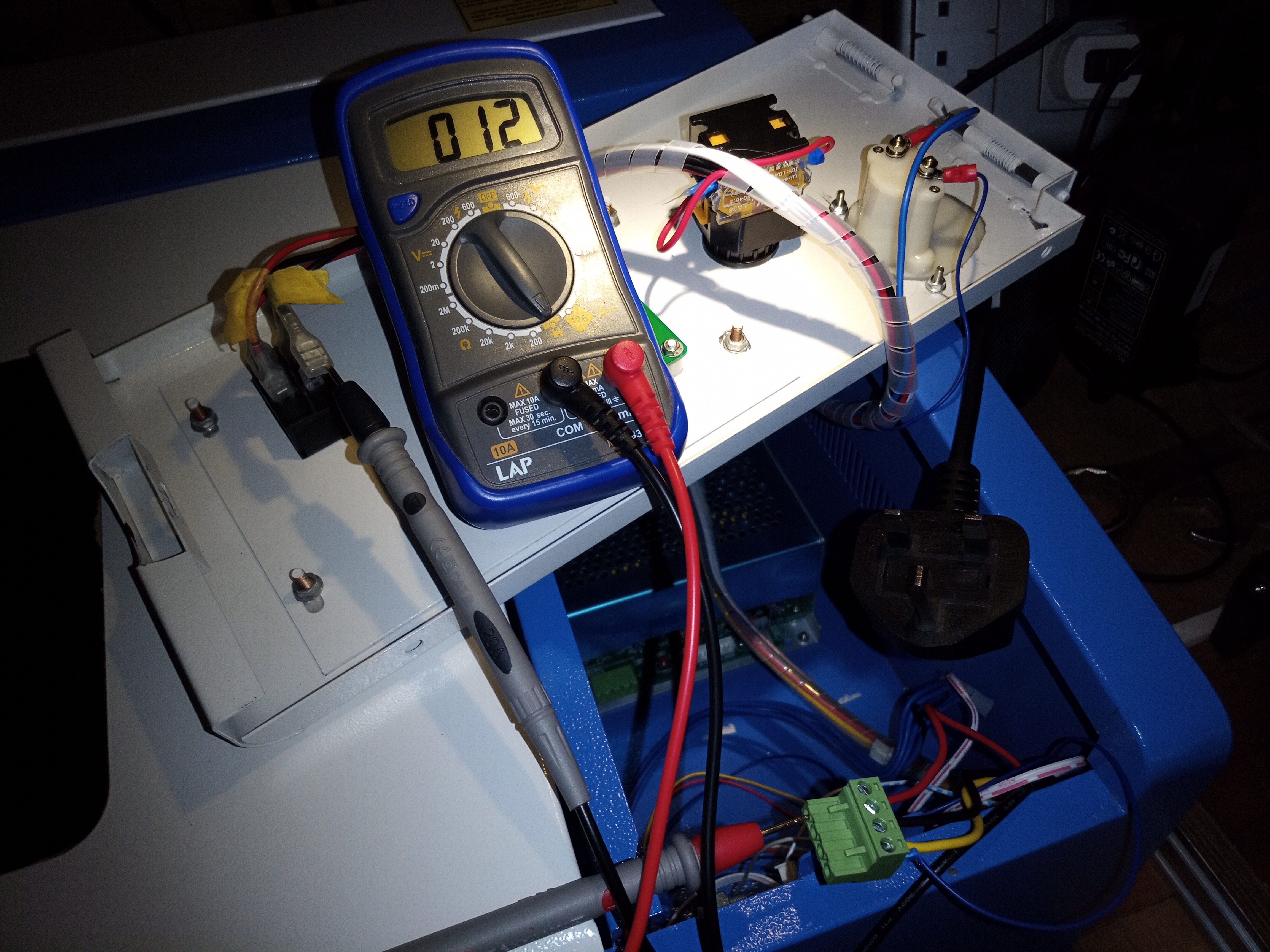
I am reluctant to reconnect the mains at this time because with the plug out and the connector removed from the LPS, the wiring seems to show a short ( or i am being stupid - not a surprise)
You can see i have connected probes to the common on the output side of the power switch and the Live of the mains connector on the PSU and get a reading ( this climbs over time - it went to 012 before i disconnected it). There is no power here, no caps to store power (that i’m aware of).
Surely there should not be a connection here ?
I have done nothing with the loom other than re-wrap it in the sleeve.
Feel free to berate me if i am being stupid
AC power has a big advantage over DC power(long long history) in that it alternates the voltage and therefore creates alternating magnetic fields and this allows things like transformers to be used. Google is your friend if you want to learn what AC power is, what DC power is and how AC power applied to transformers work.
The bottom line, a transformer is just a very long piece of wire on the AC input side so if you are trying to look for an open circuit, you won’t find that when you are dealing with transformers.
As for the smaller wire on the milli-amp meter it’s more about the wire bundle in the wire than the insulator and there’s a standard called Wire Gauge which defines how much copper is needed for a given amount of electrical current. Since you say this is a K40 and we know that there are less than 30 milli-Amps(30mA) flowing through that wire a pretty small gauge wire can be used but you do want it flexible and not likely to break so over sizing it is a good thing. I doubt the size, whatever it is, you are using is too small for 30mA.
Just reread your first post and realized that you miswired you LPS and blew a breaker on your Mains line. Since you connected the [24V,Gnd,5V,L-] wiring like this:
[24V,Gnd,5V,L-]
[—,24V,Gnd,L-]
You connected Gnd to the 5V output of the LPS and probably blew that and the 24V output of the LPS. The LPS needs to have its onboard 5V working for the laser to fire so your LPS is likely needing replacement.
Have you measured between LPS-Gnd and LPS-5V on the far right connector(on the LPS) and get 5V? Do you get 24V when you measure from LPS-Gnd and LPS-24V on that same far right connector?
I have a very basic understanding of AC/DC but was more concerned that i am basically working with the loom and this is not connected to any thing at the moment. Should it still be showing a closed circuit, as stated i am not aware of any thing but wire being in the loom.
I have’nt reconnected this as i didnt want to compound the issue before any advice was taken.
Would not miswiring have caused 5v into L- , as 24v would have been to ground. Would this have blown something that is replaceable without replacing the whole lPS, it is a fairly new unit ( apparently a customer return for whatever reason).
To spell it out more clearly, when you try to ohm out an AC input you are measuring a transformer winding so you WILL SEE RESISTANCE and not an open circuit.
The power supply is supplying power at that connector, the wire loom is not supplying power but it does have ground which is shared throughout the wiring.
So moving the 24V wire loom wire to the power supply ground won’t harm anything. Connecting the 5V power supply output to the wire loom ground will short circuit the 5V power supply output and burn up components. The power supply REQUIRES that its 5V power is functional for laser control since the laser control circuitry is 5V derived.
You are not going to do any more harm reconnecting the AC input to the power supply. So how about removing all connectors to the power supply, connecting only the AC input and the laser/mA meter return(L-) and powering up the powersupply and looking for the red LED power indicator and making the 24V and 5V measurements as listed below?
i get that i would get readings if the loom was connected to anything but it is all disconnected from the LPS and the plug us out of the wall.
This would (as fas as i know) only leave live running up through the emergency stop, on to the mains switch and back down to the connector for the LPS, i am measuring from the live pin on the mains plug. The common is is benig measured from LPS side of the mains switch (see earlier pictures).
Forgive me if not making myself clear. I will attempt to get those measurements for you tommorow (9th)
I thought you were reading the AC inputs on the LPS. So you are saying you threw the mains breaker with the LPS disconnected and now you’re checking the wiring and with the LPS disconnected you are getting something(? how many ohms) from Mains plug H to mains plug Neutral?
The only thing which could be measured from the Mains plug might be the ground or Neutral to the wire harness ground if you still have it grounded somewhere like the chassis.
When you connected the 5V output of the LPS to ground you probably blew out the LPS… Not sure why you are worried about other wiring issues which didn’t exist before unless you’ve been pulling wires and changing things.
I am feeling sort of stupid here, as i found the issue. My k40 is on a bench,against a wall and i had taken most of my measurements from inside the chasis and neglected to notice the 3 pin mains input is also fused !
I was unaware this was a thing and not come across this before even having worked with pcs and servers.
With everything back together and all leads checked and double checked, it fired up again seemingly unscathed.
I was expecting it to blow again as i am still unsure of why the continuity was reading as it did.
For anyone who may have a similar connector, the fuse pushes out from the rear of the pins through a hole in the moulding ( i used a screwdriver). This one also carried a spare fuse in the fuse holder.
Lightburn runs it and the Ammeter works (thankfully). Another job that should have taken 30 minutes taking way longer, but i am used to that since the stroke. Even a simple message like this takes 4 times as long to type, check and correct appropriately.