I want to install a water flow protector on my K40 but, my power supply has the white (Molex type) connectors and there is no P&G. The guy from where I purchased the sensor suggested wiring it into the K+ & K- terminal. This is currently being used by the test fire button. I am struggling with that bit because, in my non-electrical mind, I would think that both devices are basically “normally open” switches. In my thinking, when I press the test fire button I close the switch and the laser fires. If that is correct and I wire the water sensor in, If it starves for water the swith closes and… the laster will fire. It would be great if anyone could confirm this or tell me where to install the water sensor.
If both the test fire button and the water flow sensor are normally open switches, then wiring the water sensor in parallel with the test fire button could indeed cause the laser to fire when there’s a water flow issue.
To address this, you would want to wire the water flow sensor in series with the laser’s enable/disable circuit. This way, if the water flow sensor detects a flow issue, it interrupts the circuit and prevents the laser from firing.
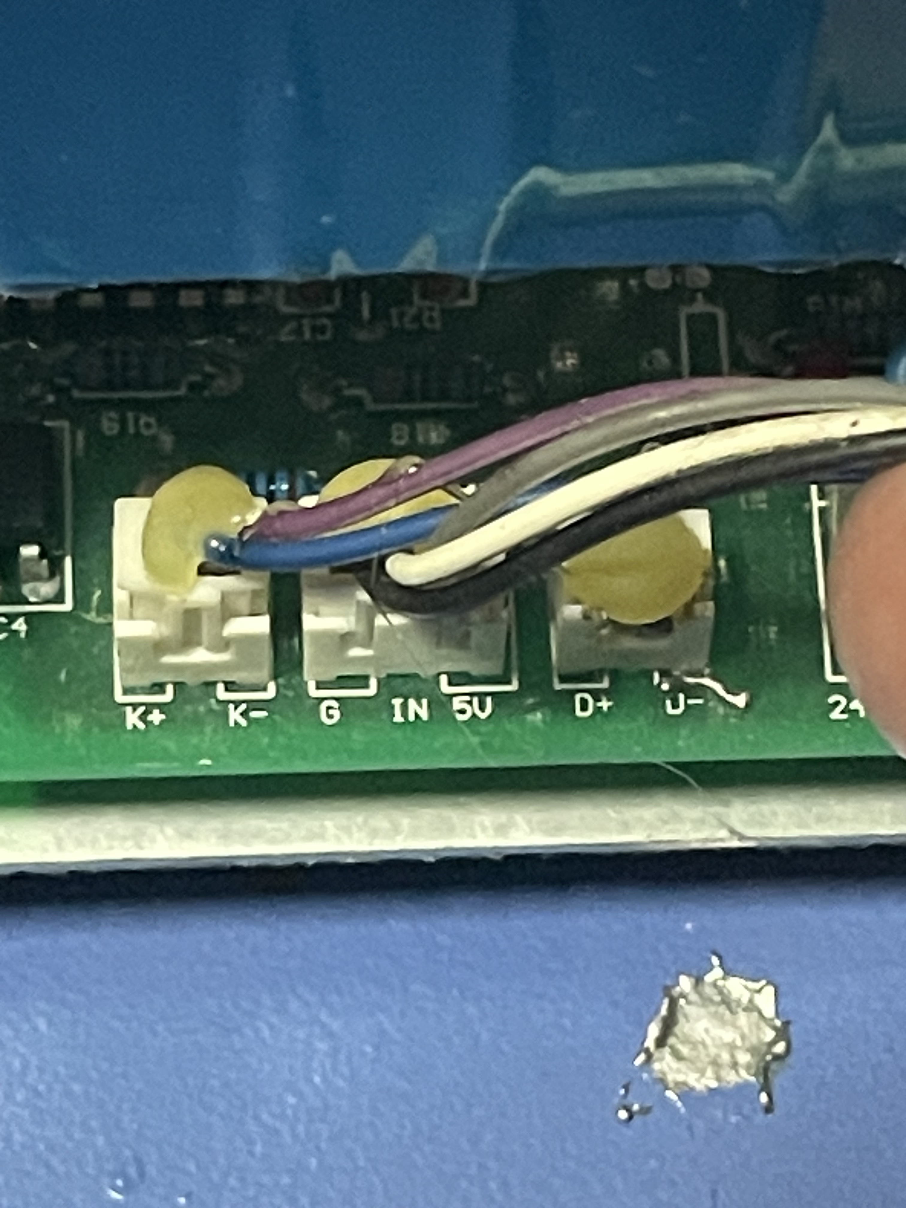
Please post a picture of the LPS showing its connectors.
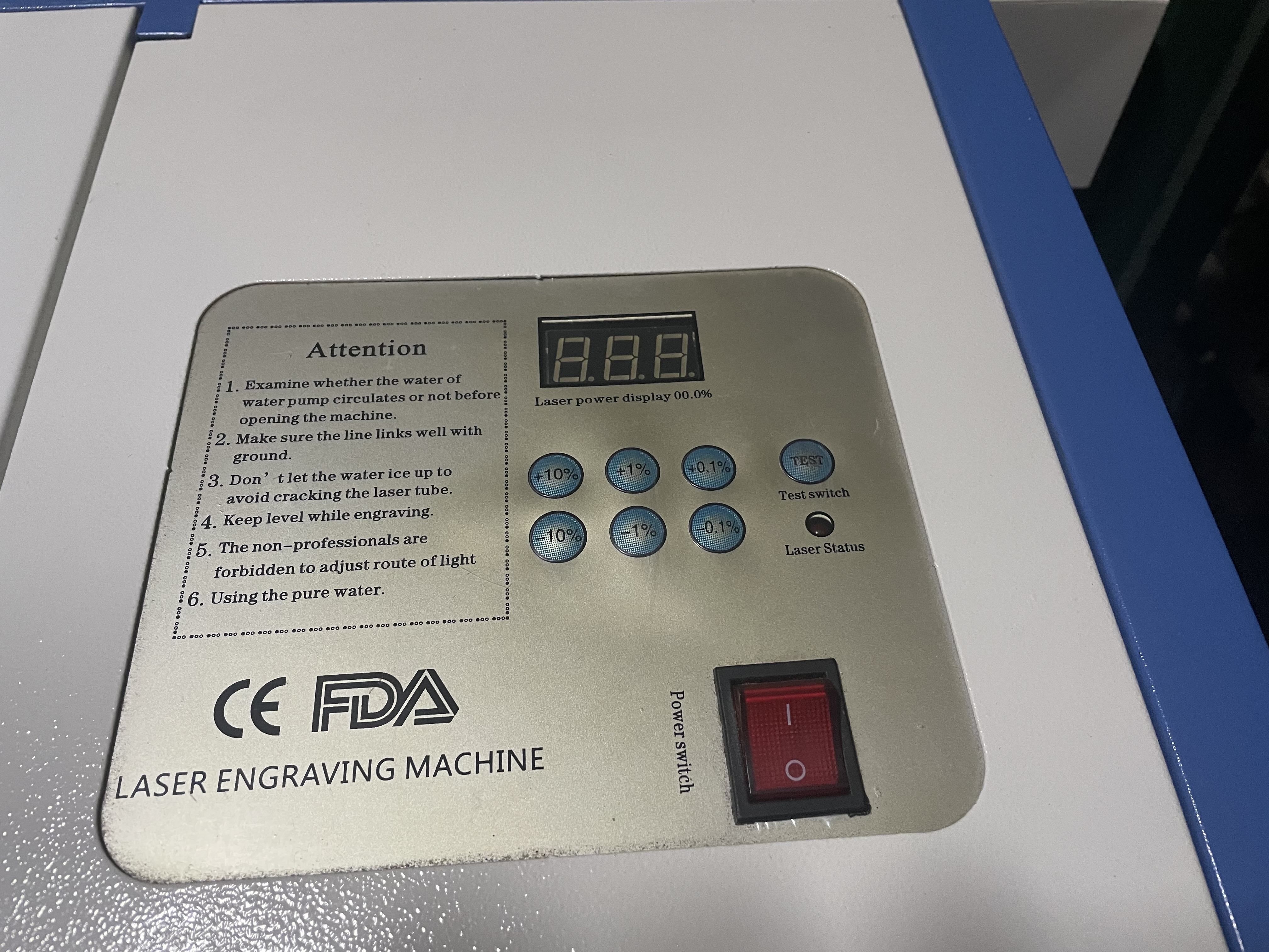
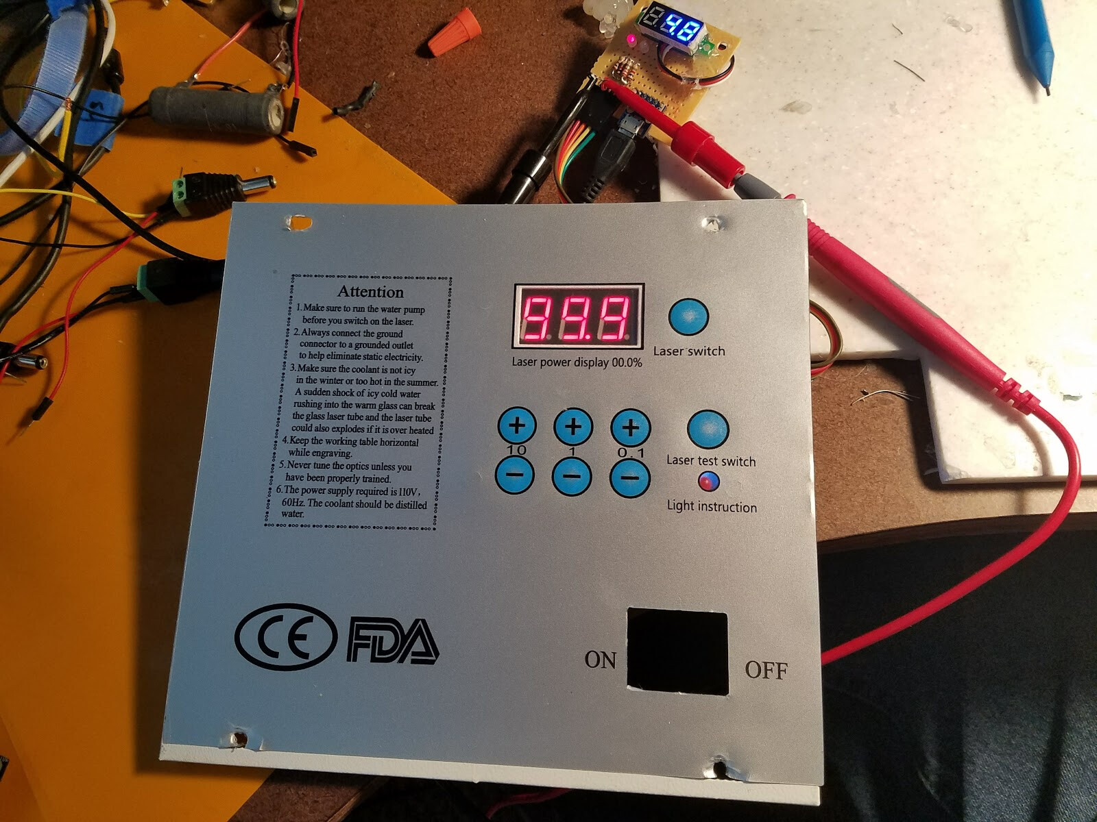
Also, post a picture of your control panel.
Typically a water flow sensor is closed when water is flowing. If the water flow switch is in series with the K circuit it will open when there is a lack of flow and the laser cannot fire.
The problem with using the K circuit is that its usually wired to the “Laser Test Switch” which is a momentary NO switch. If so, the only time the water flow sensor is in the circuit is if the test switch is pushed.
Thanks for a quick response. I purchased the flow sensor in China and was told that the K circuit would work, since no P&G is on my board. Although my understanding of how it all works in not exact, you seem to confirm my suspicions that this will not work, thank you for that.
I uploaded the photos that you requested. Thanks again for your time. Ed
You should be able to use the D+, D- for your sensor.
What I cannot tell is if there is something in that socket.
It should be shorted to enable the LPS to run.
If it is not then something is weird about the wiring.
Is there anything in that connector?
Is the D+ shorted to D-?
There is nothing in the D+ D- circuit. It is shorted with a glob of solder. I will need to find a mating connector or solder directly to the posts. Thank you for taking time to assist.
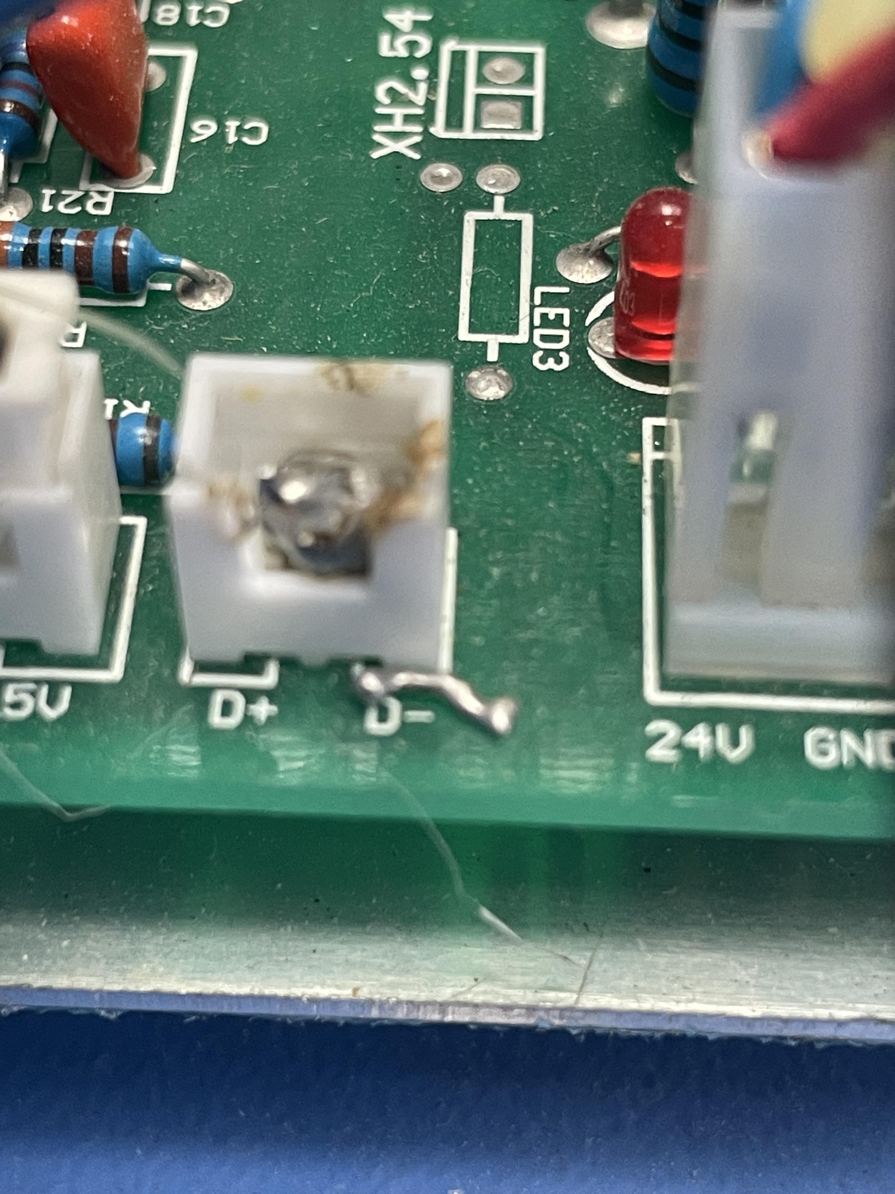
Can you post a picture of the short.
I believe those are XH-style connectors (2.54mm pitch) connectors
Here are some pigtails that would avoid having to purchase crimpers etc. You can also get full kits from Amazon.
As an Amazon Affiliate, I earn from qualifying purchases.
Thank you for this. I didn’t know these pigtails existed. I currently work in Vhina so I will try to find these here. I tried to post a photo of the terminal as it had a glop of solder across both the plus and minus pins. I’m using my phone so not sure it posted.
Thanks it did post.
If I use the “D” circuit, besides the obvious solder glob that needs to be removed, what is your take on the trailing solder below the “D Minus” leg? Will this also need to be cleaned up?
I cant really see if the solder is connected to anything. I don’t think there is anything there to connect to?
If not connected to something I would remove it.
Hello Again Don,
Interesting update on my K40 affair. I had to change the Co2 laser tube, which is why I added the water flow sensor. Then the power supply failed so I ended up replacing it as well. The pin out seems to be same on the new power unit but, wouldn’t ya know, there is a problem. With everything plugged back in exactly as with the old supply, the digital display lights up including the red laser fire button and nothing works. When I unpulg the three-prong lead indicated by “G” “IN” “5V”, the control panned returns to normal and the laser fire button works, with the laser status light only light when laser is firing. I suspect that there may be some difference in the new power unit for these three pins, yet they are marked exactly as the old one. I need to trace the three wires but there is a black wire on “G”, a white wire on “IN” and a grey wire on the “5V” pin. The only thing different is the new power supply and everything else seems to work. I was able to align my mirrors by firing the laser from the control panel with the three-prong connector unhooked.
Have you encounter such a thing before?
Thanks for your assistance…
Ed
You have both new laser tube and power supply vs the ones in the thread above?
Looking at your control panel above:
…the digital display lights up including the red laser fire button
what button do you mean?
…and nothing works
What does not work?
Hi Don,
Yes, the tube and the power supply are now new. The pins of the new power supply are same as the old one, except that there is a P&G that was not on the original. I installed everything same as before but when I power up the digital display illuminates but the “laser status” lamp, which normally only illuminates when the laser is firing, is constantly lit. When I push the laser “test button” or the up/down buttons, which increase or decrease laser percentage, the tube does not fire. It also will not fire if I press the test button directly from the new power supply. When I remove the 3-pin connector from the new power supply, the laser status light goes out, but the display is still illuminated and the laser will fire when the test button is pushed.
The three wires on this connector are black going to the “G”, white going to “IN”, and grey going to “5V”. These three wires all go up to the control panel and this is how they were connected on the original supply. The K- and K+ wires also go up to the control panel and appear to be what function the test fire button. I hooked the water flow sensor to “P&G”, which appears to be working. My feeling is that the connector pins of the 3-pin terminal on the new board may be wired differently than the original but not sure where to go from here.
Very frustrating but thanks for any suggestions.
| donkjr Don Kleinschnitz Jr. Don
April 15 |
- | - |
You have both new laser tube and power supply vs the ones in the thread above?
BigBossTX:
With everything plugged back in exactly as with the old supply, the digital display lights up including the red laser fire button and nothing works. When I unpulg the three-prong lead indicated by “G” “IN” “5V”, the control panned returns to normal and the laser fire button works, with the laser status light only light when laser is firing.
Looking at your control panel above:
…the digital display lights up including the red laser fire button
what button do you mean?
…and nothing works
What does not work?
Please post a picture of the connections on the new LPS.
To avoid confusion let’s ensure that we use the actual names of the switches in our posts.
---- Summary of symptoms ----
| Condition | Numeric Display (pnl) | Laser Status Button (pnl) | Test Switch Button (pnl) | LPS Test Sw |
|---|---|---|---|---|
| 3-pin connected | On | ON | No fire | No fire |
| 3-pin removed | ON | OFF | Fires | ? |
Note: 3-pin refers to the G-IN-5V connector
Please make the below measurements with the 3-pin connector plugged in.
Make each measurement relative to a G pin.
Instructions for filling in the table(s) below:
- For each table requested: Highlight the table in this post
- Then click “quote”
- A new post will open or for an open post text will be inserted which includes the formatting of the table in place
- Just modify the text between the two (|) formatting characters, to match your responses
---- Measurement Table ----
| Ref# | SignalName | Units | Measurement |
|---|---|---|---|
| M1 | G | Volts | ?? |
| M2 | IN | Volts | ?? |
| M3 | 5V | Volts | ?? |
Here is a schematic showing how this is normally wired.
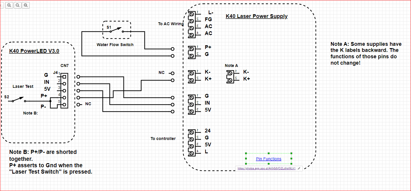
This is a reference to how the panel works:
Don's Laser Things: Understanding the K40 Digital Control Panel???
On a related note … WHOA!
When did the "laser Switch disappear from the digital panel, I missed that.
So how is the laser disabled in this case? Does this mean the laser is enabled at power-up?

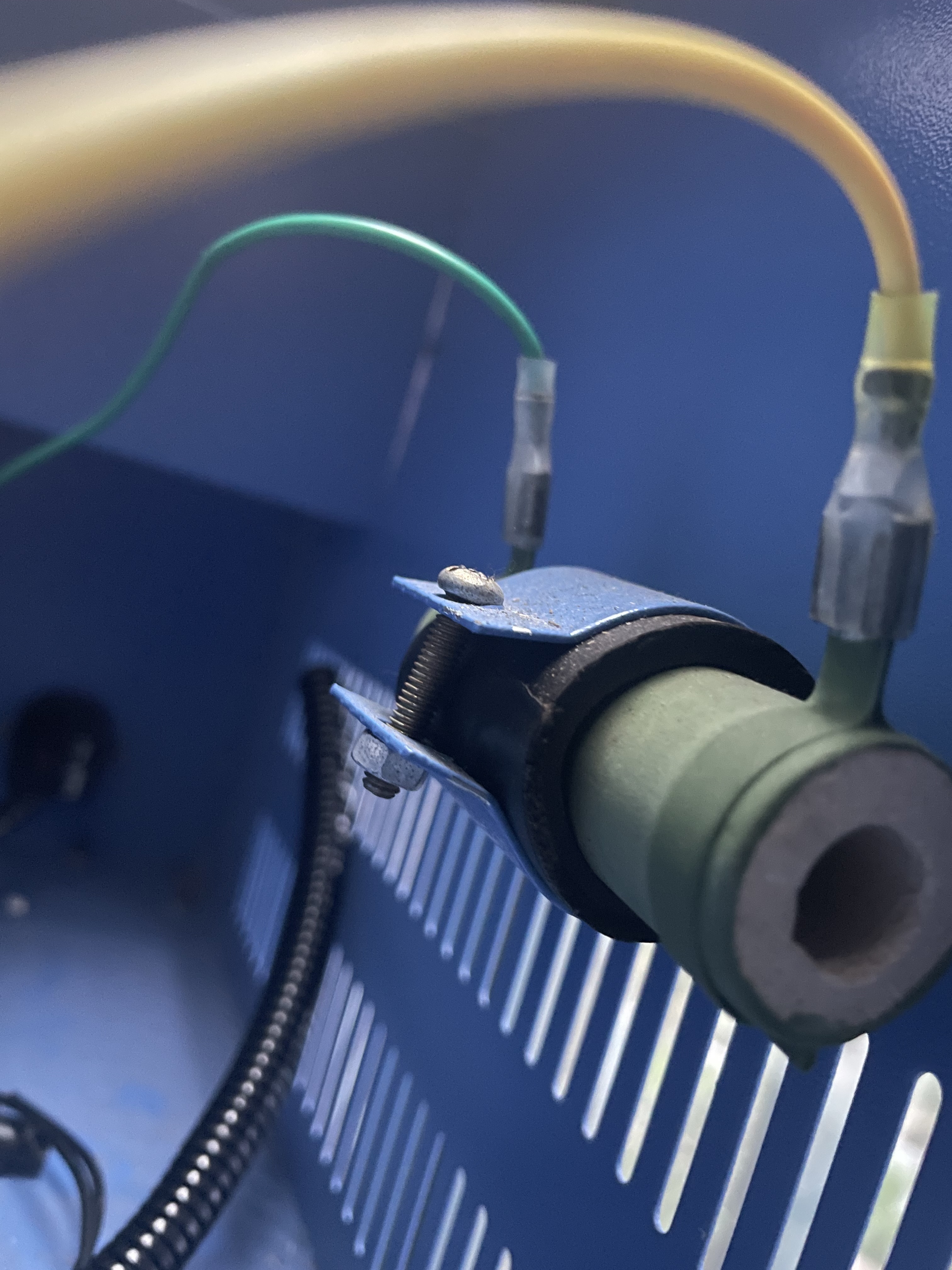
Thanks again Don… Greatly appreciated. I will be able to work on the laser again this weekend and will follow your suggestions below. My K-40 was purchased in China, which, although I am an American, I reside for work. The machine worked very well with a lot of hobby use over the past 6-years before it just started having issues with a weak tube and problematic power supply. The manufacturer is no longer in business, but this is a very weird machine all around. I noticed that most K-40’s have the laser power switch which, as you noted, is not on my machine. All of the wires to the power supply are green except for the high-power laser supply, which is red and a yellow wire to “L-”. This weekend I am planning to replace these with proper colors, and I want also to add an mA meter. There is something else that is on my machine that I have not seen on others and not sure why it is there. It is a ceramic cylinder that goes between the laser return wire to “L-” on the power supply, like where you would wire the mA meter. I will add a photo but let me know if you have ever seen this before or if you know what purpose it serves as I have been unable to find any reference to this. Again, your help and knowledge are most appreciated, and I will get back on the project this weekend.
April 16 |
- | - |
Please post a picture of the connections on the new LPS.
To avoid confusion let’s ensure that we use the actual names of the switches in our posts.
---- Summary of symptoms ----
Condition | Numeric Display (pnl) | Laser Status Button (pnl) | Test Switch Button (pnl) | LPS Test Sw |
- | - | - | - | - |
3-pin connected | On | ON | No fire | No fire |
3-pin removed | ON | OFF | Fires | ? |
Note: 3-pin refers to the G-IN-5V connector
As a rule, I do not make major changes in the middle of a problem. Often this makes the situation worse. We can troubleshoot the machine by measuring at the LPS connector, get it fixed, and then make changes from a known working machine. Your call :).
The ceramic cylinder is a ballast resistor. It was used on older LPS’s and is not needed on this new one. You can remove it although I do not think it relates to the current problem.
On a related note. I have often wondered about the value of this resistor. When you remove it can you see if there are any markings? If so take a picture of the markings. Also please measure and let me know the resistance.