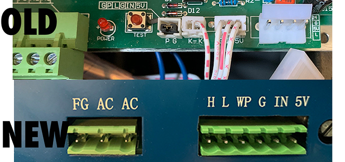
the image is the old to the new psu. Also the psu has one red wire coming from the rear of it which I can hope to assume is the ground wire.
Next to the 5V there’s a potentiometer and a red button(no idea) it didn’t come with instructions.
I cant seem to get any power to the new PSU, I started by hooking up the FG, AC, AC connections. at that point I assumed at least the psu fan would go on… it did not.
I proceeded to connect the other wires to the matching pins on the new psu.(still nothing happening though. I think the part im hung up on is the old board has an L and an L- port. The new psu does not. I hooked the L to L on the new psu and the L- to H on the new psu( is that correct?)
image for reference
