So I’m working with another machine from a different supplier than the last new one that came with the power supply not mounted and I have run into a very odd problem. When getting everything set up, I was able to get it to fire the laser from the test button the first few tries (after finding that there’s a water flow sensor that was keeping it from firing initially because the flow was too low). Now, what I’m dealing with now is that the laser will not fire from the control board on the door (with the readout and external controls), but it will test fire from the switch on the power supply. This has lead to an inability to run via the K40 whisperer software properly. It goes through all the motions, but the laser doesn’t fire when running a job. I see the indicator light on the front panel running the job just fine, but the laser isn’t firing during the job at all. Anyone have any insight on what this could mean?
There should be an enable switch. Make sure it is on.
I will look, but I don’t think I’ve seen anything of that nature anywhere on the machine separate from the obvoius switches so far.
Looked around this thing carefully and I’m not seeing any other kind of switch in or on the machine that would enable anything that isn’t already on and an obvious switch or knob. I’m starting to wonder if I’m having issues with this water flow sensor that’s been installed. I feel like there was one time where the control panel button did work, but only once. I’ve got half a mind to swap the pump out with the old one I have from my original machine, but I don’t know if that would make a difference. The company I bought it from thinks that the water flow could be an issue if it’s firing directly from the power supply, but not the control board. But there are no kinks in the tubing that I can find (I don’t like how flimsy the standard tubing is), but it’s painfully easy to get a kink, bend or fold in it. Seriously contemplating bypassing that water flow sensor, but also don’t wanna damage anything short term or long term by doing that… IF that even works.
The test switch on the LPS bypasses all other inhibiting controls.
This means that the supply is working but the enable controls are not enabled.
Try out the troubleshooting guide i this post to see if you can isolate it.
Typical things are: water flow sensor, interlocks, enable switch (on panel), wiring fault.
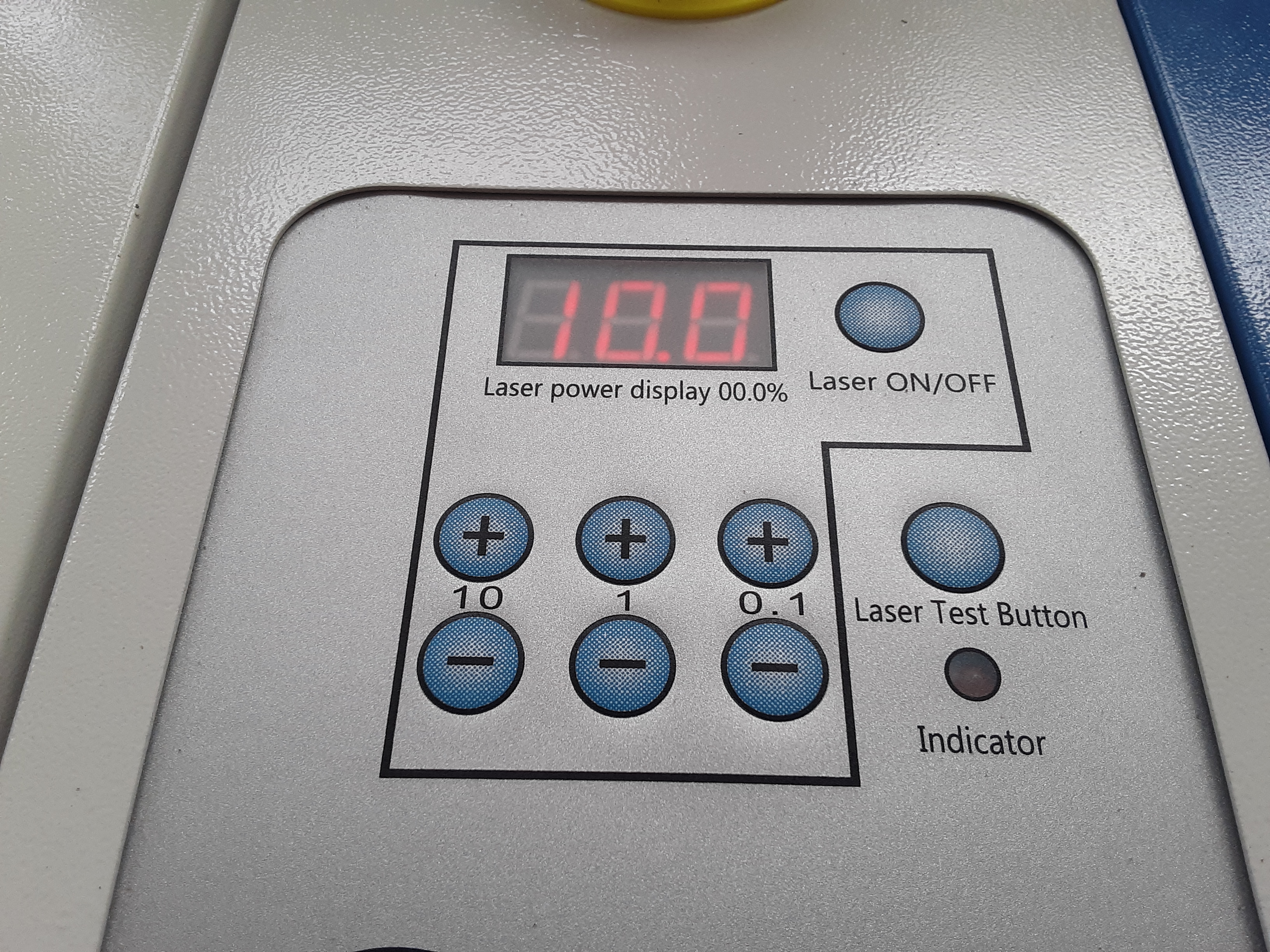
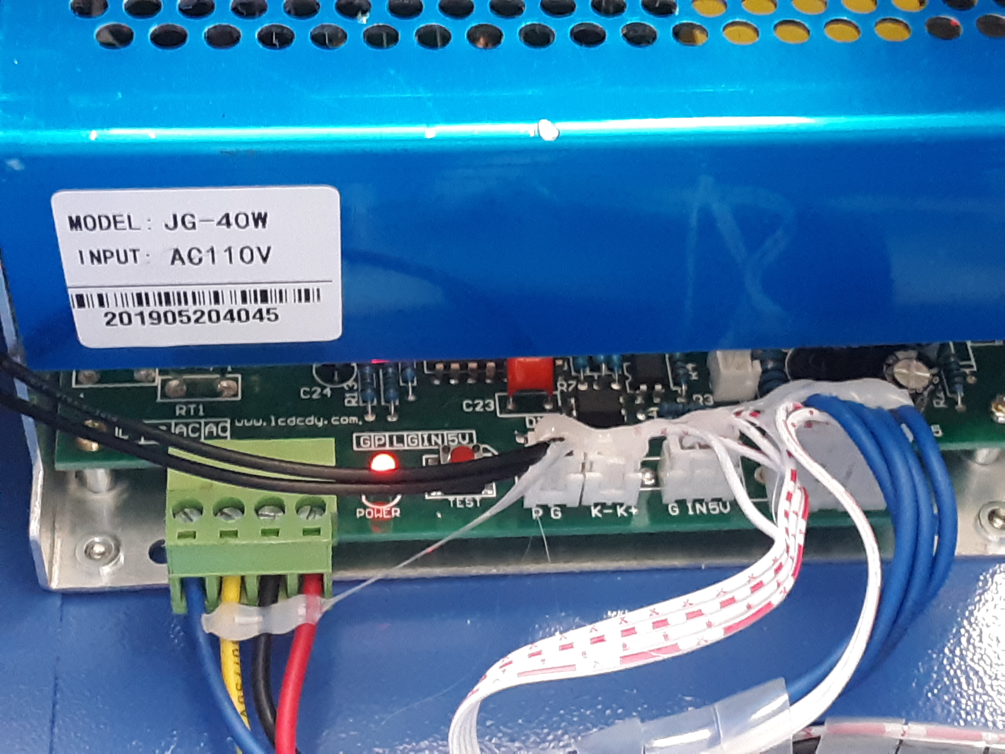
Post a picture of your LPS and panel.
Looking for something suitable to jump the connections mentioned in the guide. Posting pics as requested in the mean time.
Forgive my ignorance here. But if I pull the connector with the blue cables to jump L and G (from the guide) to test the laser, it basically turns the machine off and nothing happens when I jump the pins. When I plug the connector back in, the machine goes to home. Not sure how I’m supposed to jump those with the connector in place.
The pictures let us know a lot more about your machine.
If you go to Don’s blogsite, you will find everything you need to know about the power supply.
The connector labeled P G is the power supply enable / safety input. With the machine off, disconnect the connector and jumper the pins. Turn the machine back on and see if you have the laser enabled and working. This will tell you quickly if your flowswitch is not working correctly. I would also follow the wires on the input and see if there are other places that it leads to see if there might be other interlocks involved.
Are you saying that pulling the right most connector blue wires shuts off the machine or that the machine will not operate. When you pull off that connector the machine will not operate but that is not germane to that test.
I see that the table may be misleading as to when to have the connectors on or off.
To test the L connection on the LPS rightmost connector UNPLUG the cable.
If not already turn main power on.
Ground (G) the L pin with a short wire to see if the Laser fires.
While you have that cable disconnected measure and record the remaining voltages on that connector.
Plug the rightmost connector back in.
Power is still on.
Measure and record the voltages in the table on the 3 white connectors by probing into the top of each connector. You will have to remove the silicone globs.
There is no need to measure the leftmost AC mains connections.
List the values you measured in the next post.
I don’t seem to have a good way to jumper these pins at the moment, so I’m still not getting any change in response. I’ll approach this again once I return to the shop in a few hours.
Just for verification have you tried toggling the laser on/off button? this would be the enable previously mentioned that is a latching button on the analog machines, not sure how it works with the digital board. without this enabled the laser test button shouldn’t work nor should the controller board(grounding L) yet would allow the test button on the laser PSU to still function and fire the laser. I have never been a fan of these digital ones as they have had too much inconsistency in actual power output and can overdrive the tube.
I just tried turning the laser on/off button on and off repeatedly to see if that changed the response in the test buton firing the laser and there was no change. I am looking around my shop for an old motherboard I can pull a jumper off of to try jumping the P and G pins without the water sensor connected (which the wires from that connection only go to the water sensor).
You can always tke the blade of a flathead screwdriver to short the 2 pins and then press the test button.
Just tried that. had no affect, unfortunately.
Now trying to think of the safest way to jump the L and G on the other end since they are not side by side like P and G on the water flow sensor.
Oh well, was hoping it was something that simple heh. If you have a momentary button lying around you can wire up a trigger to test the L to G, or any wires with a dupont end can be used to jumper P to G to cut out the water flow sensor. I dont know if your like me as I have bins of components lying around for just this purpose  I would also check continuity on all the wires in case one broke internally with a multimeter in “beep” mode(beeps when a connection between the leads is made).
Fun new information! I was able to find a hard drive jumper on an old drive I no longer use and connected the P and G pins. The machine is now firing from the control board. I’m thinking the water flow sensor is actually faulty because there are NO kinks in the line at all and I have thuroughly checked to make sure of that. I will let the company know that my diagnosis is the water flow sensor is faulty and have them send me a new one. In the mean time, I will likely bypass it with the jumper to get some work done before I leave town in less than 12 hours. Fun times!
Side note: I swapped out the control board for the one from my older machine and tested that beforehand. I am going to research as to whether or not I can use hot glue on these boards to hold the connector housings in place because a few of them are not secured and that is problematic. Here’s to hoping I am able to get a functional water flow sensor and not have to bypass that!
Hot glue should be fine IMO, and glad you got your problem fixed. faulty flow sensors are both common and annoying, they seem to fail more than work, and tricky to diagnose with the white connectors vs the green ones(just need a screwdriver and a bit of wire to jumper with)
I use hot glue to hold connectors in all the time… works fine just don’t get it down inside the contacts.
The water flow sensor may also be reverse in the water loop. They have a flow direction.