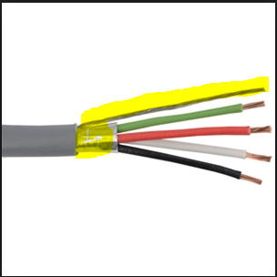
That’s right, shield connected one side, “controller” end.
Keep in mind that the shield is by no way a grounding. It’s an interference protection. It could do it on our “small” machines but keep it in mind.
If you want a proper ground, use a separate wire from your main AC power and same gauge (1.5-2.5mm or awg 14-16 ). Especially if you have elements like an AC router, heated or whatever.
You can ground your(s) 0VDC (of each power supply if many) so they share the same reference.
Edit: note that routers have their own earth wire usually
When I made my own motor drives decades ago I had to deal with noise issues. I ultimately came up with the same solution on my own that the rest of the world uses. Namely I isolated my step, and direction lines at my drives with optocouplers. Great minds all think alike I suppose?
I don’t run shielded motor wires. Because the noise can’t enter my logic system with the logic optically isolated anyways. That is the path of propagation BTW. It goes down your logic lines, not the motor wires.
It works too but adds costs, more elements subject to fail, etc. I work in automation and can count one my hand problems with EMI. Separating power (not running along) and logic/data + shield where needed (VFC, high power with high frequency switching), and all vulnerable data line (bus, analog lines, etc) will do in most case.
@Maxime_Favre
I want to see you run two stepper drives without optical isolation together. Been there, done that, it just don’t work. This is why every stepper drive manufactured has their step, and direction lines optically isolated. Because that does work. The cheap ass TB6560 boards are optically isolated. The TB6600 drives I just bought are all optically isolated.
@Paul_Frederick I understand and agree with you. Btw since opto are already in, nobody will remove them
I’m talking about EMI in general, not only steppers. Add a VFC drive which many spindle use and depending the power you’ll regret not using shielded wires.
@Oyvind_Amundsen
I guess it might help with other sensitive electronics? I don’t listen to an AM radio in my shop while I’m running jobs though. So any EMI noise that might be coming out of my CNC machine doesn’t really bother me. PWM motor drives are some pretty spiky bastards too.
Thank you all - great help.
I have learned a lot while working on my DIY CNC project. I have asked questions like this hoping that other users can learn from it…
Next step is to decide what spindle to use - 1.5Kw that can be cobined with my Toshiba VFD.
@Oyvind_Amundsen
what spindle is best depends on the kind of work you plan on doing. There’s no one spindle that can do everything. I wouldn’t for instance choose a 30HP induction motor to isolation route a PCB. Although that same motor would prove ideal hogging a high volume of ferrous materials.
This scheme of one and only one path from any point to earth (shields tied at one end only) is standard practice in pro audio for noise immunity. It is known as a star ground system. Ground loops are caused by stray current due to resistance variations between multiple paths to earth. Only one path, no chance of loops.
 (this is not mine, but I plan to make mine something like this)
