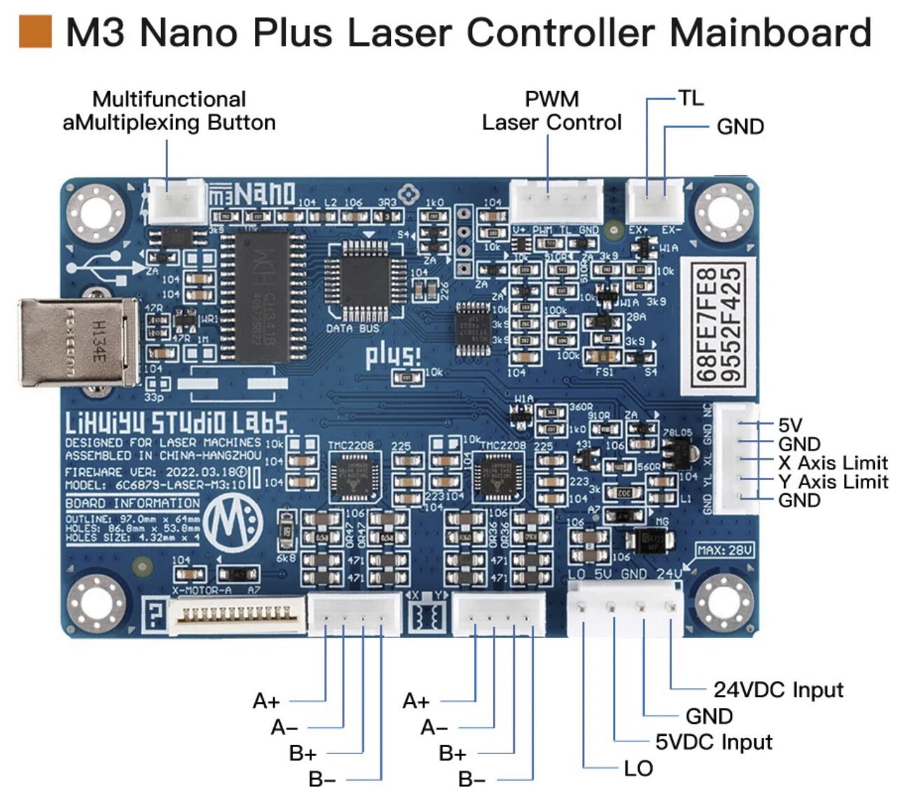
L is your laser enable pin.
Do you have a question or problem?
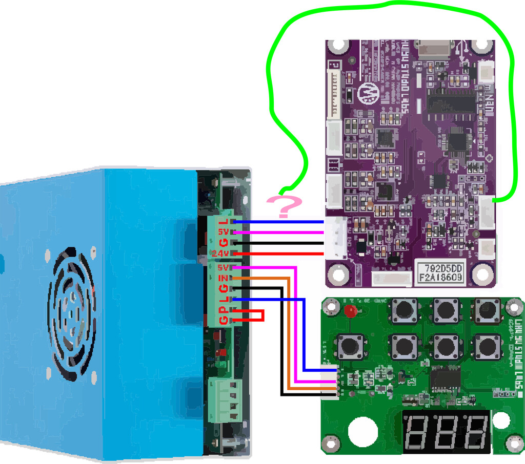
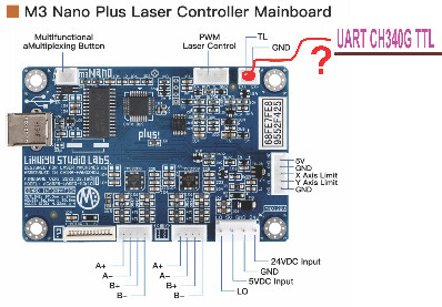
M3 Nano PWM Laser Control connection diagram to PSU is unknown.
That PWM is on M3 Nano board connects to PSU of the laser machine through wiring, but in what specific way?
We take a bit of time every couple months looking for either new Chinese software or reading the chines documentation. While it might be reasonably possible to hook up the PWM correctly, namely you have a chip there in the upper right that is controlling that and the controller lines hook directly into the CPU chip
The chip below it at V+ with the 6 arms thing is actually the relevant chip there basically that should give you an attenuated power signal to use in line with the knob. As such, we previously figured it out but there wasn’t much need for it because we do not know what software commands trigger this.
A - Serial Challenge Code.
B - Right
C - Twitchless and Slow mode.
D - Laser On
E - Part of SE kicks in Compact mode.
F - Finish triggers the 236 on done when it hits.
G - Raster step code. 2 codes do non-equal stepping.
H - Unused.
I - Reset
J - Unused.
K - Unused. (Probably, the controller sent AK0 sometimes)
L - Down.
M - Diagonal move inside compact.
N - New. Kicks off different rapid mode commands. Returns to Rapid Mode.
O - Unused.
P - Pause/Resume, part of PP home command if both paused and resumed. And S1P.
Q - Unused.
R - Up.
S - S1 S0 and S2 state values.
T - Left.
U - Laser Off.
V - Velocity, specific to starting speed code.
W - Unused.
X - Unused.
Y - Unused.
Z - Unused.
We figured that the power command should be something like Q127 or something for half power and there were only so many ascii keys possible but we literally tried them all. We sent a bunch of different made up commands to try to trigger the power at a reduced value with a volt meter hooked up and we could not crack it. We could also wait for the Chinese software to reveal the correct answer, if it sends and attenuated signal command we could easily duplicate that but honestly we (the Meerk40t devs) do reverse engineering of this as best we can and we cannot figure out any method of triggering the command.
"The PWM 214G chip is driven off of CPU pin 16, through S4 (not sure, Schottky diode?), 10k resistor, to 214G pin 1. - - - With a 104 capacitor to ground between S4 and 10k. "
The little six armed chip is a 214G the other big addition is for the multifunctional multiplexing button which uses a JC3H7 Opto-isolator
This one, however is a lot easier. You trigger the switch and when it’s in compact mode it causes an infinite look toggling between a couple different states causing a hardware pause. The opto is so that signal attached there doesn’t feed into the CPU and cause any issues.
But, the CPU to 214G chip is the harder thing to figure out since we need to trigger a change in the CPU and frankly we do not know what command could do that.
There’s some indications that a M3 will not automatically turn off between cuts sometimes when you use a @ command whereas a M2 totally would, which implies that maybe it’s preserving a PWM setting between those. But, nothing ever came from our research there.

The TL hook up there is turned on during a cut and for about 8 seconds afterwards (changed to reduced time for the M3). So first you can’t drain that much voltage or it will end up getting the laser stuck firing (which is quite unsafe) but if you hook it to a relay or whatever you’re good. It will turn on when the laser is cutting or doing a laser job and will turn off about 8 seconds after the laser has finished firing. If you wanted to hook your air assist to that it would be quite reasonable and would only turn the air on when the laser was running. But, it only provides some secondary information about when the laser is on or not, and does not accept any input. You could probably hook up a simple LED to that and see when your laser was firing.

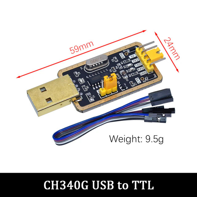
That chip is a CH340G it’s a generic serial connection chip you could plug it in whereever you want to plug it in, the question is what are you trying to do and why? You get power, and voltage out and TX and RX but what are you hooking that to. The chip there is very generic it lets you send signals out the back end to TTL, I don’t know what you’d hook that to. I mean, in theory, you might be able to hook that to the active port but there’s no indication what that does but in theory some chip rewriters would use that and maybe you’d be able to do something. But generally that board doesn’t typically do anything on the M2 M3 nano but the board is super generic and you can basically set it to do a lot of things.
But, by default the M3 Nano already has a USB to Parallel port 1.9 chip so it can already take in USB info. And I’m not sure what you’d do with that other board but I don’t know any known uses for it.
Windows to recognize M3 Nano as device connected to virtual COMx
It shouldn’t. Not unless the chip is soldered wrong for the board. It should detect it as a Universal chip and on connecting the software should tell it to be a Parallel Port. But, it should certainly not work as a serial chip unless you specifically told the chip to act that way. The M3/M2 board uses a CH341A or so and is set to EPP1.9 early on when talking with it.
M3 Nano board CH341A can be programed to work as serial device?
It could, but the Lhychip would then do nothing useful.
")
Basically the CH341 on the device hooks to the processor in a parallel mode. The data is sent to the processor like it has a parallel port but it’s just hooked to the output of the universal usb chip. If the chip was hooked into serial mode, it would need a chip that was expecting a serial connection to it.
The chip connects to the USB and then is set (either by a USB control transfer, or soldered) into one of the modes it supports. Then you can communicate over USB to a parallel port or serial port or I2C setup etc. The chip is a universal generic chip that lets you talk with that chip and do things. The same chip is used for Moshiboards, for various EEPROM readers etc, for some stuff with Arduino etc. It’s a common chip. I have one sitting on my desk that’s a simple stand alone chip. It’s so you can control things over USB and it does the interfacing from USB to whatever you need.
Here’s the very nice manufacturer data for the chip.
The chip you have the USB CH340G does the same but just does serial UART rather than having the other would-be output data types. You can do a lot with it but it sort of expects that you’d be using this for serial communications. And if it’s not hooked to anything then nothing would respond.
![]()
Yeah, that’s how the device typically shows up when plugged in with the standard windows driver. From there you’d use something like meerk40t or the chinese software and control the laser. Or install K40 Whisperer which would replace that driver with a LibUSB driver.