Looking for I2c expertise to check and improve my modifications to the I2c master for ESP (using SDK, not Arduino) - 4x faster already + clock-stretch - can this be improved… http://tech.scargill.net/faster-esp-i2c/
I ain’t no expert, but by removing the delays you’re changing the bus’s clocks. If you ever wanted to interface with a device that can handle max 100KHz I2C-clock, for example, your code would stop working and you’d have to reintroduce delays accordingly to get the right speed.
Everything I can find can handle a lot faster than that - so up to now it’s worth that possibility - I’m not making a general purpose I2c bus - just a mechanism to add specific devices in. By the time I get a timeout on the stretch I could see the bus speed averaging 400k. I think rather than slowing that down by introducing variable speed I might just if needed have 2 function blocks - good point though.
Understand the fasted spec is 3 meg - no chance of achieving that.
i2c works at speeds up to 400khz, and 1.something Mhz on some devices, check the datasheet for the devices you’re attaching or provide an extra config parameter when initializing the interface to specify the speed. Also, consider some devices like i2c eeproms need a little time say 10 ms after each byte write.
For higher speeds usually SPI is used instead, with spi you can reach 10Mhz duplex or that at least is the higher I’ve seen on a datasheet. Check these for reference: http://ww1.microchip.com/downloads/en/DeviceDoc/20001952C.pdf http://www.atmel.com/Images/doc0670.pdf http://www.onsemi.com/pub_link/Collateral/CAT24C128-D.PDF https://www.nxp.com/documents/data_sheet/PCF8574.pdf
I’ve fiddled quite a bit with the SPI-library for the ESP8266 Arduino-core, including writing some optimizations. There is a 64-byte FIFO-buffer (accesses have to be 32-bit aligned, though, or you’ll crash the ESP) for the SPI-bus and you can actually put out 80Mbps max. I have only managed to read data in at 40Mbps, though I haven’t done much testing on that part as I was more interested in putting pixels on an SPI LCD as fast as possible.
Hi guys - sticking with I2c, (I have a display running on SPI on the Arduino). Don’t want to use up another wire and some of the cheaper devices only come I2c. It is looking like 400Khz then
I suggest you have a look at my code. I have some years experience with I2C and I use it to control lots of different devices, which makes it hard to get it right but also has a large learning potential…
A few facts that might be interesting: 1) you can only drive the bus as fast as the slowest device connected. If you go faster than the slowest device, it will get confused, resulting in hogged sda and even scl if you’re unlucky. 2) be very careful with toggling sda. Sounds straightforward but isn’t. For instance when you need to generate a stop condition, the sda may be low or high at that point (depending on previous data). Don’t just set it low, it will be seen as a start condition. Insert a complete scl-sda cycle instead. 3) don’t pull sda one instruction after scl. At high speeds this will introduce over-speed glitches. Pull scl, wait, pull sda, wait, release scl, wait. With the proper delay you can still obtain 100 kHz operation, and up to 230 kHz (400 kHz in 160 MHz mode). If you’re going to fiddle with i2c I suggest using a logic analyzer to check all timings. Inc is not critical for clock speed, it can vary between every bit, but at no time it can be above the max speed of the slowest device.
Look for esp8266 universal i/o bridge on github. Don’t have a browser atm.
BTW you “cannot” just use 400 kHz. The slaves need to be switched to fast mode before every transaction. Having said that, I never do that and it just works  YMMV…
YMMV…
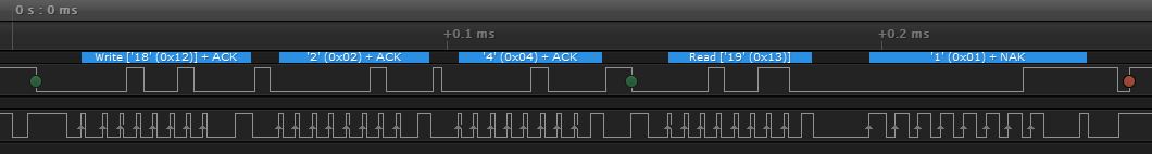
Looks like you’re already using an analyzer, familiar one! The clock duty “should” be 50% BTW to be sure you don’t have overspeed glitches.
@Erik_Slagter Funny you say that - ONE of my devices (i2c port expander) seems not to be working now - all the rest are working fine… could be unrelated…
Could be or not What device? Maybe an MCP23008/MCP23016 or a PCF8514(A)? The MCP can work at up to 400 khz without specific adjustmens, the PCF can’t. I use the MCP23016 to drive an LCD. To get acceptable performance on the display it needs to be driven at max speed.
The I2C “driver” code from Espressif itself is horrible. I really wouldn’t use it or take it as reference, like many people seem to do.
I had to use it as a starting point because other stuff is generally written in C++ for the Arduino- Indeed there is one that is written in assembly for the Arduino but the assembly directives simply will not work properly in my Eclipse environment in C.
ERIK - PCF8541 - so are you suggesting that this device may be my problem (before I start doctoring my I2c code) - I’ve around 8 devices here all working and the only one that for some reason has stopped is this port expander based on the PCF8541…