tommorow i have a digital volt meter
i don’t think it has a water flow sensor where should i find the water flow?
tommorow i have a digital volt meter
i don’t think it has a water flow sensor where should i find the water flow?
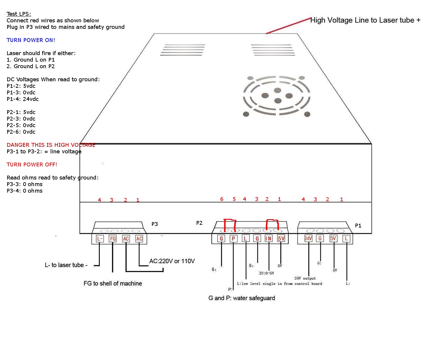
This drawing represents your LPS connections.
The water flow sensor is typically connected in series with the “P” signal on P2-5.
You can short P [P2-5] to G [P2-6] and then press “Laser Test Switch” [on the panel] to see if it will fire. That bypasses anything that is disabling the LPS.
For now, ignore the short in the drawing between P2-1 &P2-2.
What is the model number for that LPS?
Is this what you mean?
I take the brown cable out of P2-5 and put it in P2-6?
The model number of the LPS I didn’t find
No
Please read instructions carefully…
This means to install a wire between those two terminals.
Please read the instructions carefully…
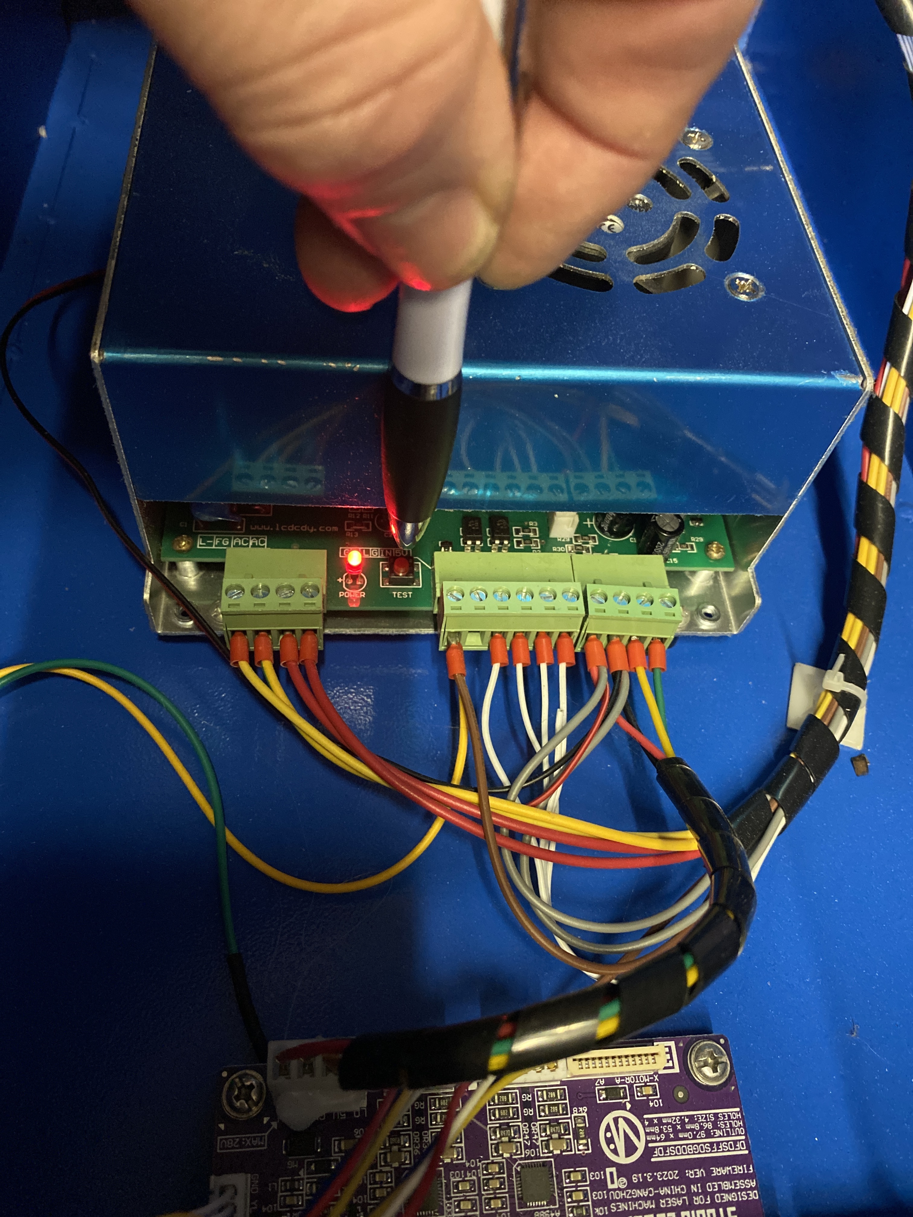
That switch is not the “Laser Test Switch” on the panel!
We already know that the TEST switch down on the LPS will fire the laser, correct?.
We are trying to find out why the "Laser Test Switch" on the panel does not fire the laser!
When I Connect the cables to eachother
Then the laser test switch is working
Is there something I must do now?
To be clear:
…when you short P [P2-5] to G [P2-6] and then press “Laser Test Switch” [on the panel] the laser fires?
Yes or NO?
If YES;
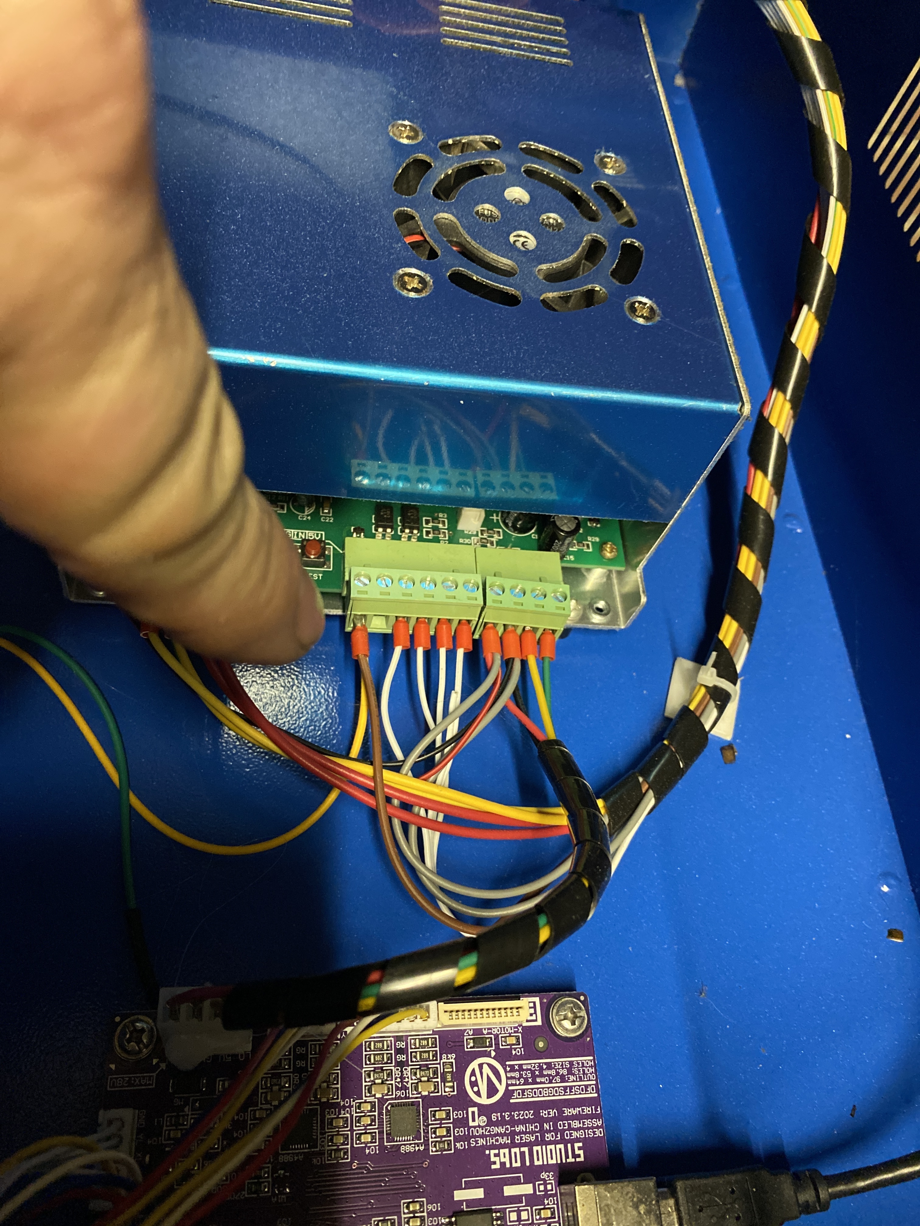
There is likely something in series with the brown wire on “P [P2-5]” that is open-circuited.
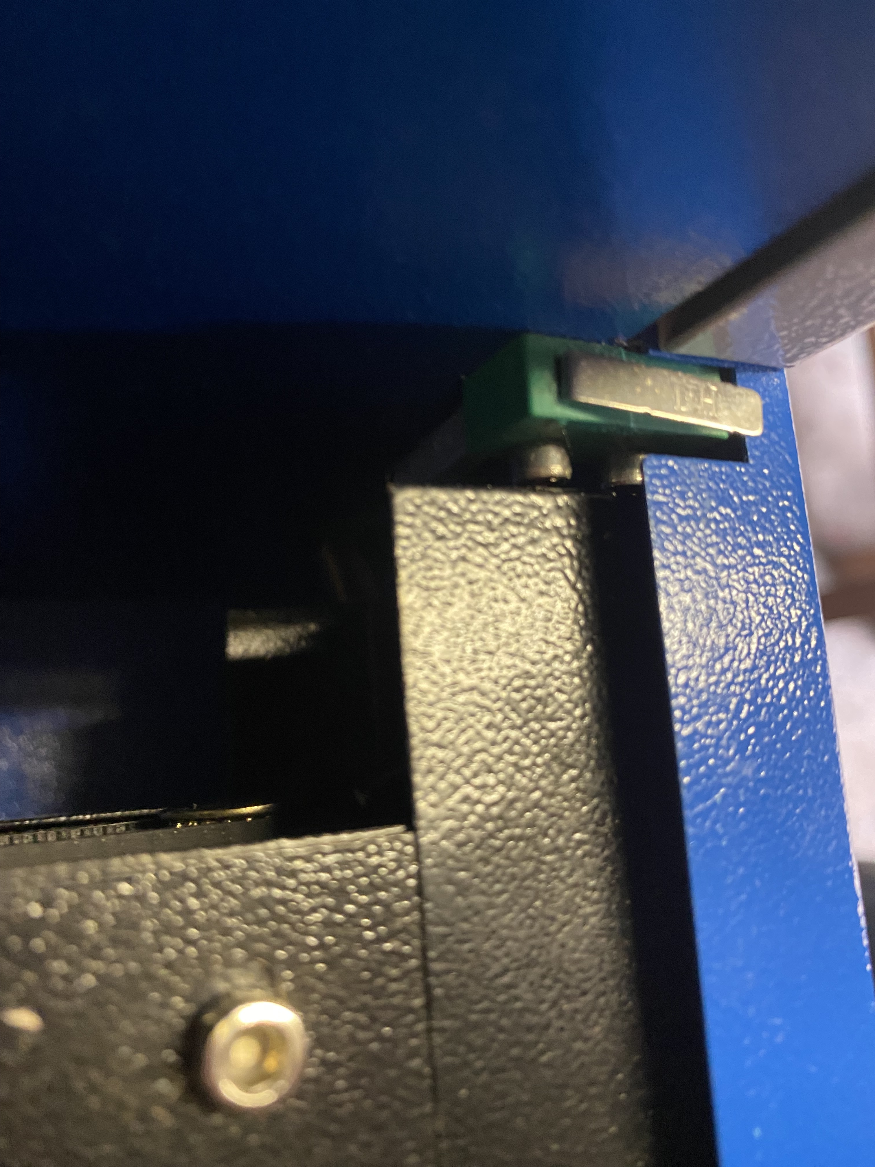
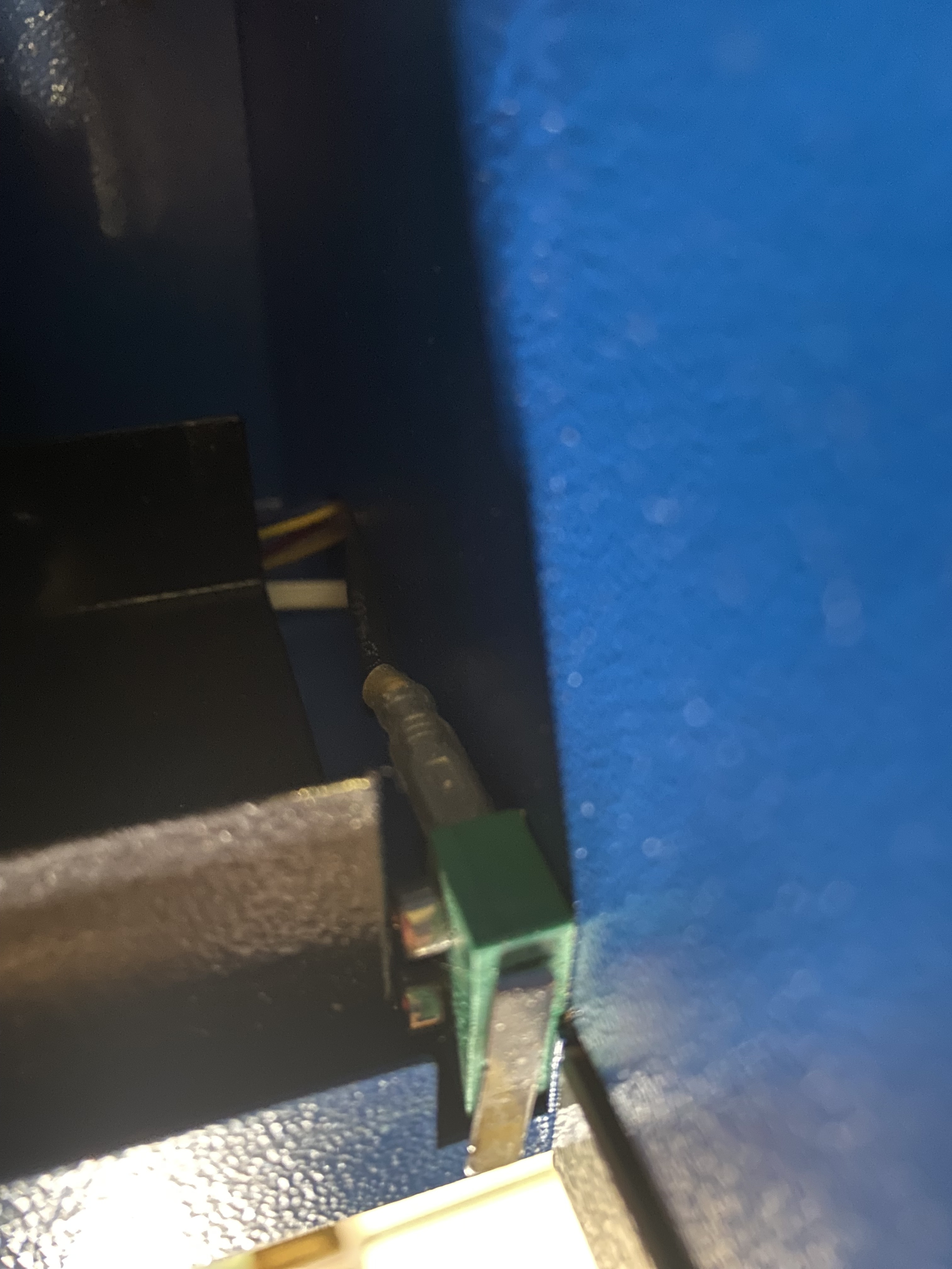
Trace the brown wire on P2-5 backward from the LPS and see what it is connected to. It could be an interlock switch or a flow switch. Take pictures of any devices you find connected to that wire.
It may look like this:
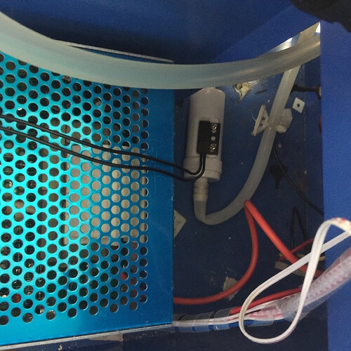
A water flow sensor would be in line with your tubes cooling circuit (tubing). It would be a device with tubing connected for input and output. It would have two wires connected to it.
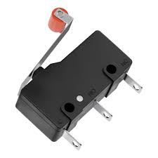
An interlock switch might look like this:
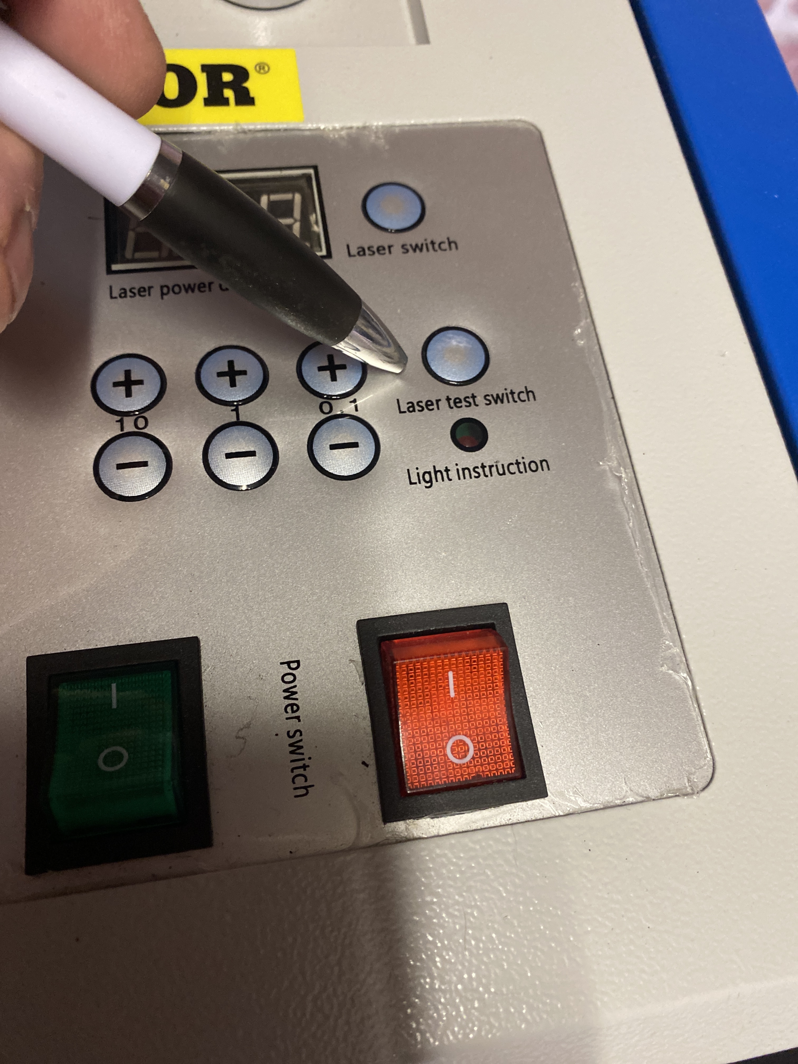
Is that brown wire connected to the RED “Power Switch” it looks like it from the pictures above.
The machine will run with the P signal shorted but IT IS NOT SAFE. This means that the machine may ALWAYS have the laser-enabled. I DO NOT recommend running this way since any unexpected control signal can fire the laser.
It doesn’t make sense to me [yet] why that brown wire is in the gantry harness. I suggest unwinding the black cover on that cable to find out where it is terminated.
Have you looked everywhere for a lid switch or water flow sensor?
Hi Don
I have look around
s that brown wire connected to the RED “Power Switch” it looks like it from the pictures above.
Yes it is
The Brown wire is also going to the door switch
See photo please
That is strange.
What is the purpose of the red power switch? i.e. how did you use it when the machine was working?
What is the “Lighting” switch for?
From your description the Red power switch and the cover have to be closed for the laser to fire…?
If you close the lid and the “Power Switch” does the laser then fire from the “Laser Test Switch”.