I’m having some troubles with my k40 laser cutter. Long story short: it will not fire the laser on either the test switch button or the button on the power supply. I contacted Vevor, who sold it to me, and they very kindly sent out a new power supply and laser tube for me under warranty on the assumption that it would be one of these two items that was faulty, but I am still without a laser. There is also no sign of life in the analogue current indicator, regardless of the position of the regulator knob.
The light on the power supply lights up when turned on, and the switch for the lid of the cutting area also seems to be correctly positioned.
I’ve had a quick play with the safety switch using my multimeter, and it all seems to be ok, in that it’s an open circuit with the lid open, and has continuity with the lid shut (I mention this because some of the equipment at work is completely counterintuitive with some of the switches!)
Good afternoon, and sorry for taking a while to get back to you.
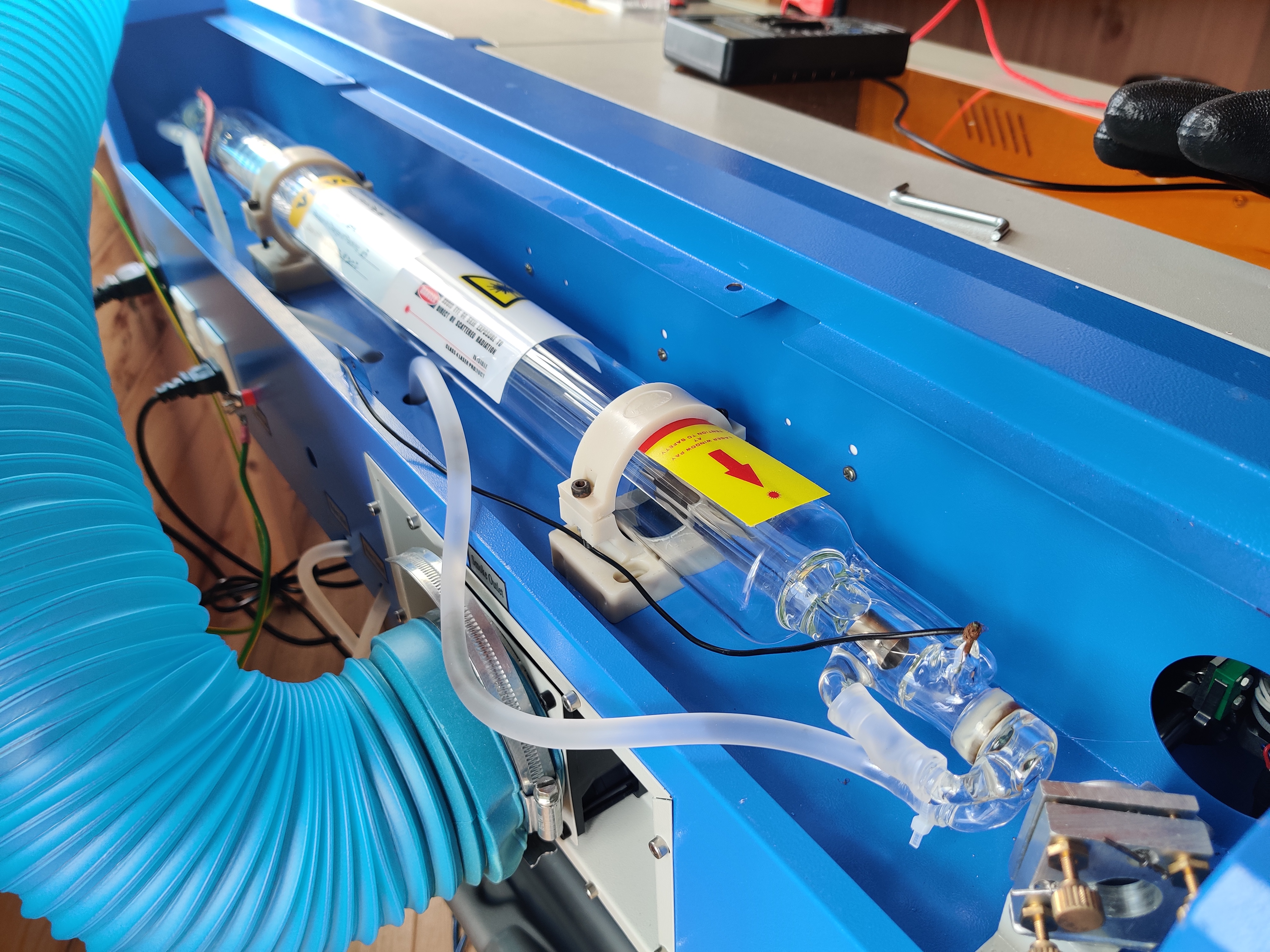
I do have a multimeter available, and have been using it primarily for checking continuity. I have just checked, and it appears that there is power being provided by the power supply to the tube when the test button on the power supply is depressed, as shown in the photo
Whoa, that is extremely dangerous!
That supply outputs 20,000VDC and is lethal.
I do not know where you are measuring but I suggest you do not continue.
You cannot safely troubleshoot this problem at the laser tube. We will do so indirectly by measuring the state of the LPS’s control signals.
Here is the pinout for that supply.
With the meter measure and record the voltage on each pin of the right two connectors relative to the ground.
Edit
Has this machine ever fired?
Did you do the upgrade to Mini Gerbel V3?
Did it fire with the stock controller?
What does the taped-off white wire connect to?
It looks like you have the controller PWM signal connected to IN of the LPS.
What does the other end of the black wire on the “L” signal of the rightmost connector connect to?
Yet;
If the IN pin is not connected to the POT you cannot expect it to do anything?
I did not fire it with the M2 nano it came with, as my computer would not recognise the M2 for love nor money, hence the immediate switch to the mini gerbil 3.
That wire lead to the L0 signal on the mini gerbil 3 board (power in)
That leads to the great big loom, potentially to the current regulator potentiometer (!?). This seems rather odd looking at it. I followed this tutorial for the installation of the mini gerbil 3: https://youtu.be/DF-FZ0MUXkw, the relevant bit is at 1:17
Those measurements are quite unusual and if accurate are incorrect. There should be no voltage > 5v.
Please measure 5V to the ground and take a picture of the face of the meter while taking the measurement. Post that photo.
Then Perform this Test:
On the right connector
Disconnect pin “L”
On the central connector:
Disconnect pin “In”
Connect a jumper wire between 5V and “In”
Warning the laser may fire (we hope) so wear protective glasses and close all covers and interlocks.
Push this test button, the one down on the power supply
Ok then now we know the laser and LPS are good :).
My guess is the IN pin is being held down (0V) by the controller.
I need a day to review the MiniGerbl vs installation.
In the meantime, we can try an additional test to verify the correct “Laser Test” operation from the control panel and without the controller.
Power off
Disconnect the previous jumper from 5V to IN and put aside. Do not reconnect the IN pin to the controller.
Instead: Reconnect the center pin of the pot (current regulation) to the IN. I think that is the white taped wire. Visually or with an ohm meter, verify that the wire is connected to the center post of the pot.
Turn the pot to its middle position
Power on
Engage the “Laser Switch” … Danger! this enables the laser to be fired. Protect your eyes!
Press the “Test Switch” the laser should fire.
Also ;
Post a picture of the back of the control panel clearly showing the wiring.
Some interesting results here. Using the ohmeter, it seems that the previously taped wire is indeed connected to the potentiometer. The laser fired as soon as the laser switch button was depressed in this configuration. I didn’t push the test switch button at any point, and the proof is in the post-it note attached to the mirror.
Top is main power switch
Top left is laser switch button
Top right is test switch button
Bottom left is current indicator
Bottom right is current regulator potentiometer
Sounds like something is holding the LPS in the arm mode or there is a mis-wire regarding the Laser Switch and Test Switch.
I have to trace some wires in the pictures but in the meanwhile, you can capture our current wiring and re-measure the control levels on the LPS.
At least now we know all the parts are good. I think we are getting close to solving this one .
Without changing anything.
Take and post a picture of the wiring just like this one:
This is correct. The switch marked ‘laser switch’ is latching, and the ‘test switch’ is momentary
Circled in green,
4th pin from left (G) brown wire: this goes to the test switch (momentary)
3rd pin from left (L) brown wire: this goes to the test switch (momentary)
Circled in Red,
2nd pin from left (P) light brown wire: this goes to the laser switch (latching)
1st pin from left (G) green wire: this goes to the safety cutoff switch for the lid of the unit.
While doing those tests, the red 5V cable (right connector) had a little bit of play in it at the other end. Tightened it up, and what do you know? We have a laser firing on the button!
I guess my big remaining question is what happens with the little grey cable from the Mini Gerbil 3 board that we disconnected, and will that have any bearing on the computer’s ability to control the cutter?
That wire heads to the mini gerbil 3 board, to the L0 pin of the ‘power in’ connector
[/quote]
The above black wire (L) is the control from the control board.
I would recommend that you leave the grey wire off.
Control of power is accomplished via that L pin being modulated.
Power limits are best set with the pot. We can discuss this when we verify all is working.
So run some test jobs so that we can tell if you are working.
You previously said that you used install instructions for the control board from Awesome Tech. Please share the link you used.