My K40’s served me very well for a bit over a year. I recently rebuilt it to have a larger interior cutting area, and moved all the power components outside the case. After reconnecting everything, most aspects seem to work exactly correct: the motors track as expected, and the laser test-fires correctly, both from the button on the power supply and the button on the control panel. However, the laser does not fire correctly when controlled by software like K40Whisperer or MeerK40t.
The laser fires at the set power when pressing the fire button on the control panel or on the power supply.
The motors both work correctly, tracking where the cuts should be.
When trying to engrave a raster image, the laser does not fire at the expected power. It’s so low that the analog ammeter only barely wiggles, you need to be really inspecting to notice, but extremely faint burn marks appear on the test material corresponding to the darkest parts of the image.
There are no marks when I instead try to run a vector cut, but the motors still move the head in the expected pattern.
I’ve used a multimeter to ensure that there’s continuity from the control board to the power supply. I use a secondary 24v power supply for the control board, it worked great before I pulled out the electronics and the fact that the motors track correctly seems to indicate that it’s still working correctly.
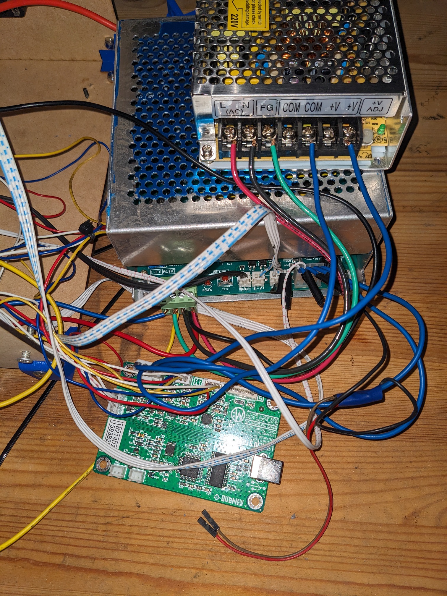
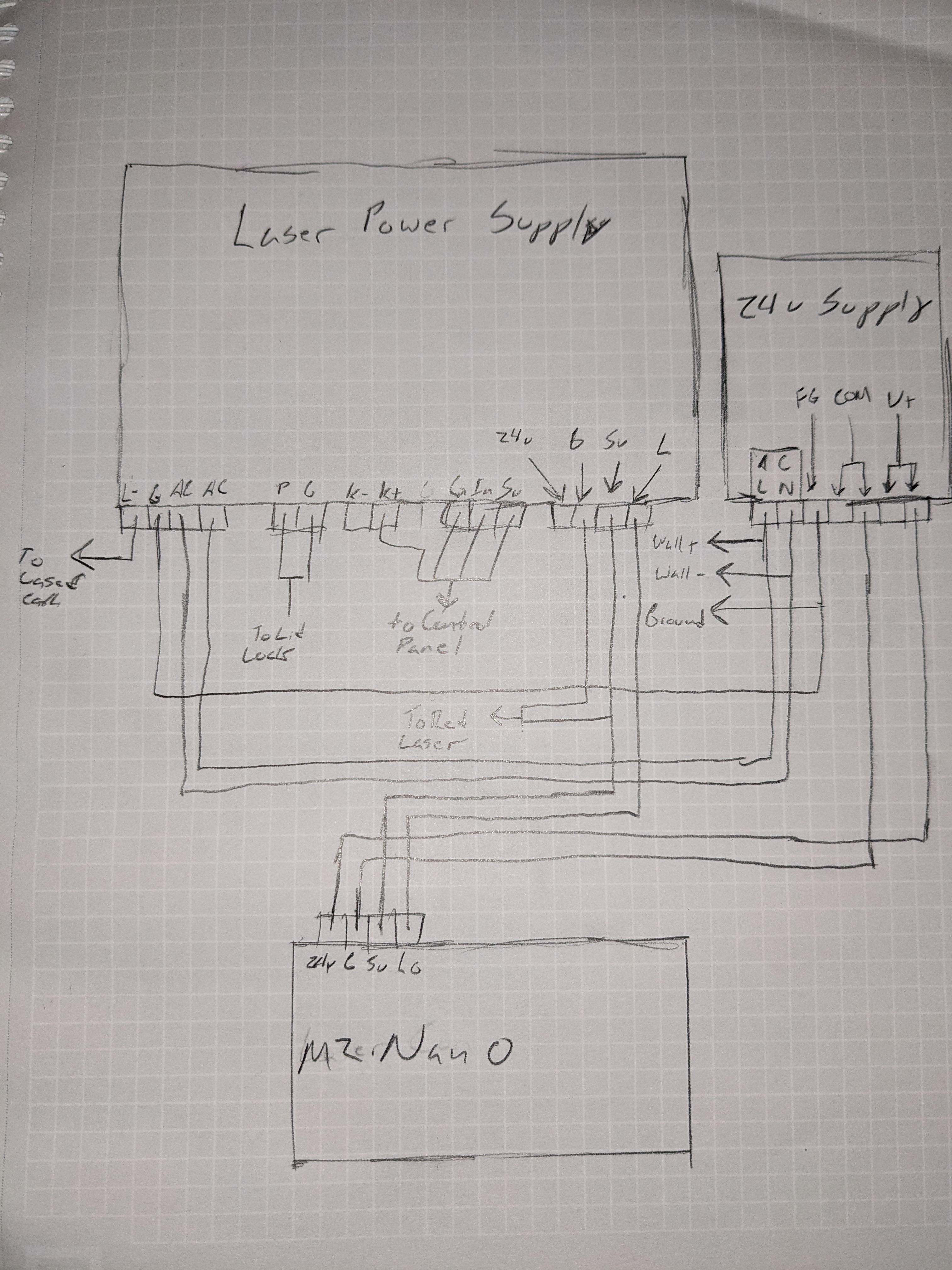
I also assumed it was an issue with the controller to the LPS, but I’ve verified that connection a thousand times. This is the wiring overall (I know it’s a bit of a mess):
You can clearly see that the “LO” output on the controller is connected to the “L” on the power supply. I even checked that connection via multimeter, testing from the pads on the other sides of the PCBs - that connection is good.
Something is getting from the control board to the supply, as when engraving there are faint marks visible on the test material and the ammeter jiggles very slightly.
I saw this thead that seems to describe a very similar issue. In that thread it was a grounding issue, but as you can see, my 24v supply is already connected to the LPS ground, which is grounded both to the case and the main ground. I have continuity from the 24v ground screw to the ground plug on the main power cable, and the outlet ground also tests well.
I didn’t follow a guide for setting up the 24v supply, it’s pretty straightforward, and it was working previously.
Is there some reason you needed to add the extra 5V supply?
It appears to me that you have a 5V supply going to the 5V supply line of the lps… The lps 5V is an output. Generally not a good idea to wire up outputs together without some way of balancing them. You should only need a ground between the supplies…
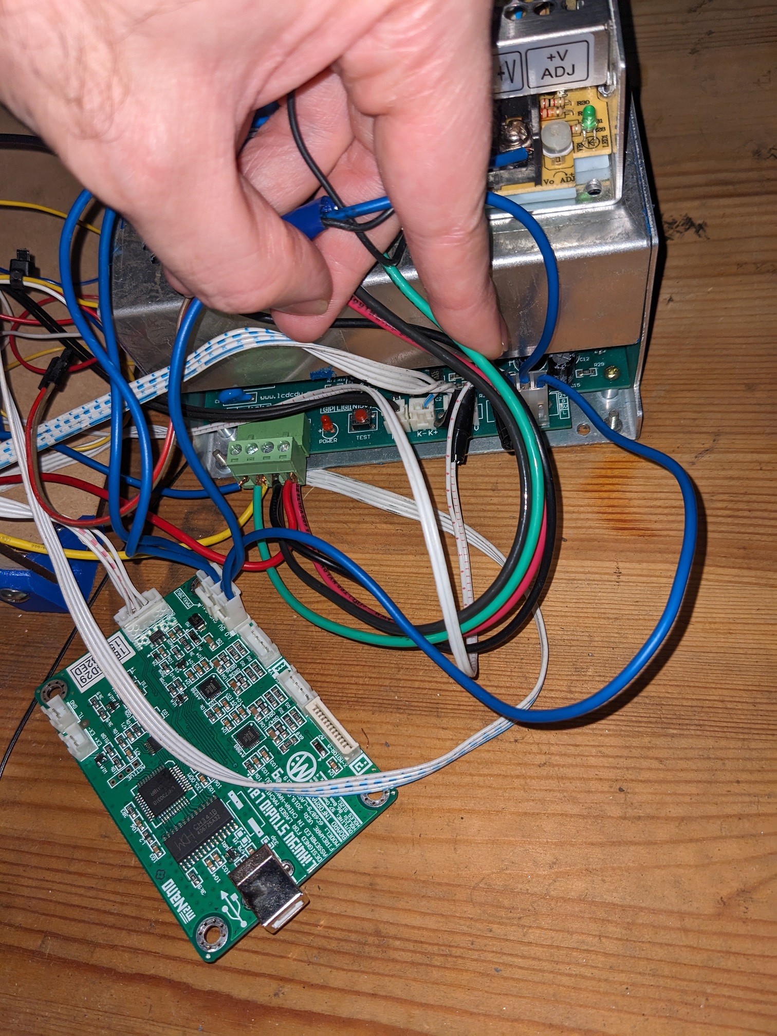
Where does the black wire, spliced to the blue 5V line go??
The only 5v supply is the one built into the LPS. The control board requires both 5v in (for logic) and 24v in (for driving the motors). The 5v out from the LPS goes to the 5v in on the laser control board, the 24v out on the 24v supply goes to the 24v in on the control board.
I installed the 24v supply last year, after reading about how the LPS the K40 comes with isn’t really designed to power both the motors and the laser tube at the same time, and immediately began getting much more accurate cuts with more consistent depth.
There is a red wire spliced to the blue 5v wire, the black wire is connected to ground, and is taped to the blue wire (along with the red) in an attempt to keep things neat. They’re both just floating with jumper ends, when fully assembled the 5v sighting laser plugs in there.
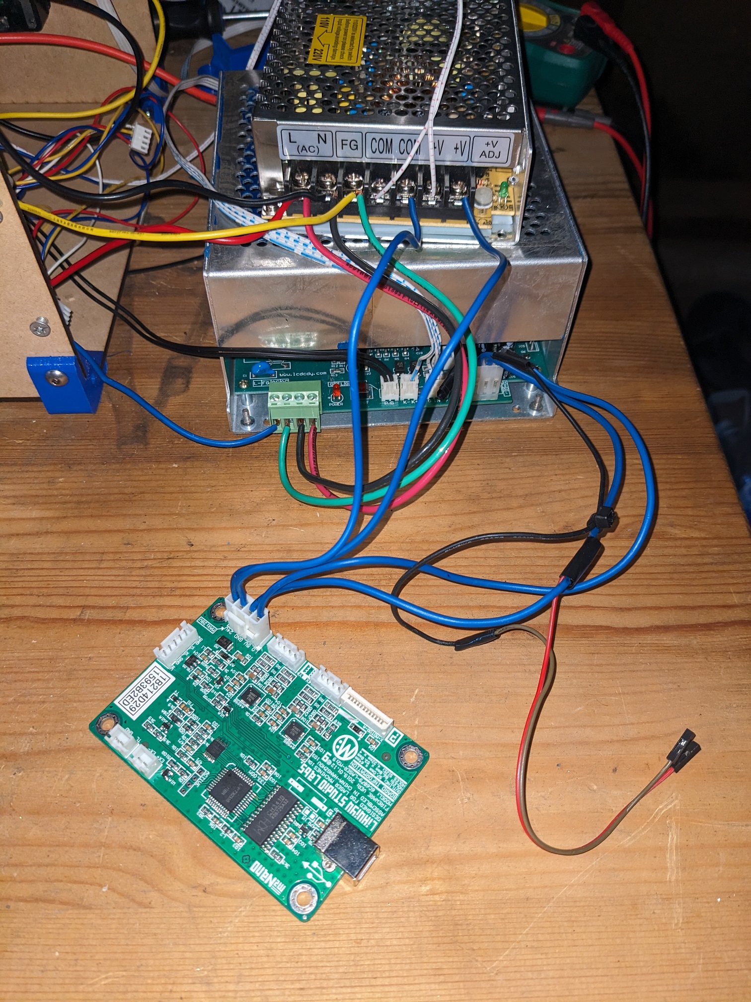
This is the wiring cleaned up further, with the end stops and motor connections removed from the control board:
There is no continuity between the 24v COM and the laser’s G. In fact, there’s no continuity between the 24v COM and the 24v G (although there is continuity between the LPS - and LPS g). And this seems to be the problem!
Previously it worked because the control board was mounted to the metal case which was connected to ground. Now that I’ve moved all the electronics to an external case, it’s no longer grounded. I connected the PCB’s grounding pad (the screw hole nearest the control board’s power inputs, you can see that the plating is connected to the board’s grounding shield) to ground with an alligator clip, and it works perfectly!
Now that I’ve figured it out it’s no big deal to run a wire from the board’s mounting screw to ground, but does this mean my 24v supply is faulty? Should I be wiring the 24v G terminal to the 24v COM terminal?
That COM/minus isn’t connected to FG/earth by default is normal for generic low-voltage power supplies. I think all my low-voltage power supplies are like that.
I’d connect 24V PSU’s COM/minus to LPU’s G/FG/L- (they are all the same). Well, I guess it doesn’t really make a difference since everything becomes FG/earth either way, but I think the intent is clearer if you connect the two 0V pins.
In electricity, unless you are doing wireless/antenna stuff you must have a circuit loop for every signal.
It’s easy to find the problem when you look at a signal output line and try to find out how the current from that signal gets BACK to the board sending the signal.
So, look at the L output of the M2Nano to the LPS and you can see there is no return path. Connect the M2Nano Ground to the LPS G( between 24V and 5V ) and you’re done. You should not be relying on the casings of the devices for ground. Signal ground is different from chassis grounding.