Hi, I have problem with our K40 laser. The laser is always on. When probing with the multimiter, there is 3.2V on the controll pin of the power unit, even when the controll board and the panel is disconnected. When measured on panel and the controll board the reading is 5V, so they are probably ok. I have tried 1K pull up resistor on the controll pin with no luck.
Also alredy checked:
grouning: every ground pin seems to be connected to chasi and to protective earth on the main plug.
lose wires: checked all wires, replaced some ferrules.
This is our secod power source, with the same problem, so I kind of hope that it some other solvable problem, otherways the K40 eats power suplyes faster than it cuts…
Make any changes just before this problem occurred?
Stock or modified machine?
Pictures of…
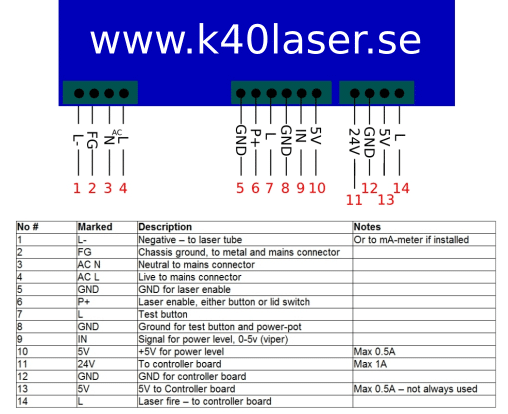
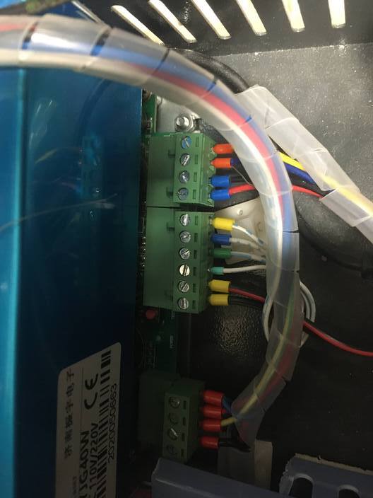
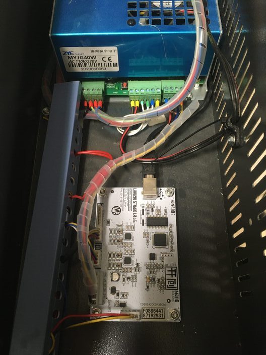
LPS showing the connector side and wiring.
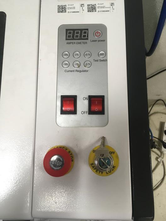
Control panel front
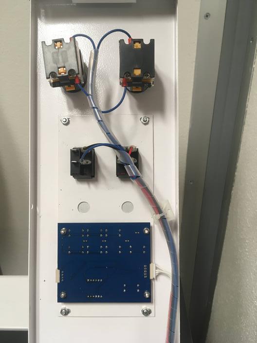
Control panel back
Symptoms:
Does it fire immediately when the machine powers on?
– If not when?
Does it behave like this within all the input connections [except AC power] to the LPS removed?
On what pin are you measuring these [name or picture]
Some hints:
For a LPS to fire, it needs**:
All the enables to be asserted: usually P/WP/K/H/L**. Usually a ground enables them. The laser is typically enabled with a button on the panel and a closed coolant switch.
With all the enables asserted. The laser is usually fired from a controller on the L pin or a test button on the control panel.
IN sets the power but does not itself initiate a fire it only sets the power level.
I have seen LPS’s that have shorts or bad parts at the supply keeping them on but usually, it’s a problem with the wiring. Since this is the second supply behaving like this I would expect the problem to be elsewhere.
Last week, but with some transition period, when the machine sometimes work correctly and sometime not.
Some local distributor but at the end from china.
No changes were made direcly befor the problem occured.
Some modification were made: added light, industrial chiller, pressured air from lab distribution system and chaged the LPS from Type 2 to Type 1, now added 1k resistor between pin 13 (5V) and 14 (L).
What does it do if you remove LPS-7 white wire and where does that come from?
On another subject, not about laser firing, you do not have an ampere meter on that machine and it has a digital power control interface which is known to be very inaccurate and good for over driving your laser tube and ending its life early.
See the “K40 Intro” link at the top-right of this page to understand more about both of these issues.
Already read the intro, and I’m aware of that, the ampere meter is on its way, but right now the laser is not od much use, and I gues that adding a meter won’t stop the laser form firing.
Also moved forward and added a separet power source for controll board. So now only GND (12) and L (14) is connecting controll board and LPS. When the LSP is switched off, I measure 5V between GND and L, when switched on it goes to 3V, also tried to remove the L (12) but stil 3V.
The control signals on the LPS are NOT TTL. All [except IN] controls on these LPS are connected to the cathode of a LED in an optocoupler. This means that they expect a hard ground (0V) to turn on. Voltages measured at these pins when open are somewhat arbitrary as this is measuring an open circuit with the other end of that LED pulled up to the LPS 5V (10).
That said, I would expect these values to be more like 4+V.
This lower-than-expected voltage could mean there is enough current being drawn on the pin to turn on the optocoupler. It’s also strange that all the control pins are lower than expected.
One could jump to the conclusion that it is a bad supply but since this is the second one doing this that does not seem likely.
Let’s keep that observation in mind as we move on and further isolate the source of the problem.
The L(7 and 14) pins are connected inside the LPS. Typically L(7) is used for the test button and L(14) is for PWM from the controller.
Why did you add this resistor? It pulls up the cathode of the LED in the optocoupler to 5V. It makes it harder to pull L to the ground. It should not be performing any function except creating heat!
Symptoms:
Does it fire immediately when powered on: yes
It does not fire only when I switch Laser power. To Clarify: does this mean that it does not fire if you only switch on the LPS?? If so how are you switching only the LPS on?
It also fires when both the controll board and controll panes are disconected on the side of the board, in order to keep enable connected. To Clarify: does this mean that you unplugged the control panel and the controller cables that go to the LPS? When these are unplugged the LPS fires at power on. I don’t understand what you mean by “enable”?
To be complete:
With the machine wired as normal and power ON:
What voltage does the 5V(13) on the LPS measure to GND(12)
What voltage does the 5V(10) on the LPS measure to GND(8)
With the machine wired as normal and power OFF:
What is the resistance between the GND(12) on the LPS and the GND on the controller?
I see two possibilities here:
There is a bad part or short in the LPS pulling the control lines toward gnd. Two bad supplies?
There is something external to the LPS pulling a control line to ground yet our measurements do not show that.
Let’s start with proving #2 true or false
Test1: Is the problem internal or external to the LPS
With power OFF:
At the LPS disconnect all the control & low-voltage power lines going to the LPS. These include: pins 5-14.
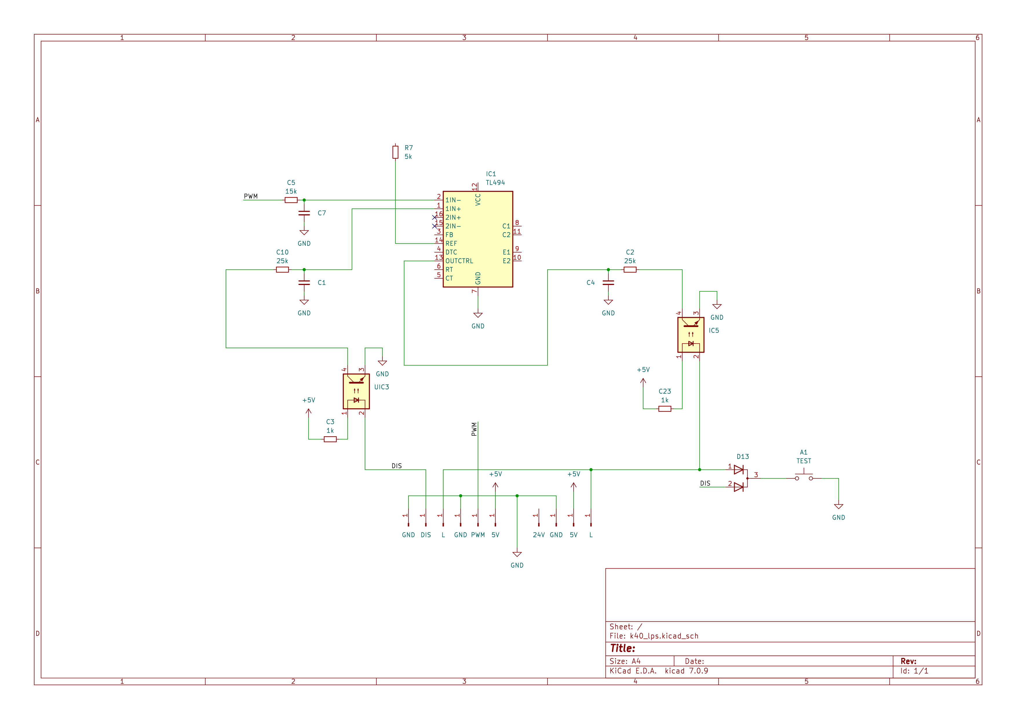
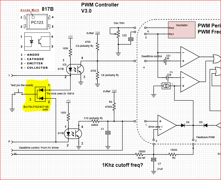
I have removed the resistor, didn’t know the circutry. Yesterday I have disasembled the old LPS so now I know, didn’t found it alsewhere so here is the crude schematic of the connections up the the controll IC:
The GND resistance between LPS and controll board is 0.6 Ohms, which is the same as when I connect the leads of the multimiter…
5V line seems to have stable 5V everywhere.
When pins 5-14 are unconected, the laser don’t fire. The voltages are as expected (all to GND):
L: 4.2 V
5V: 5 V
PWM: 4.2 V
P+/DIS: 4.2V
When I short the safety pins (5 and 6) and nothing else is connected the laser fires, and voltages are (all to GND):
L: 2.8 V
5V: 5V
PWM: 2.8 V
P+/DIS: 0V
I think that this rules out short as it appears only when the safety is not activated, bad part is stil in play.
Also, my blog has lots of details if you haven’t been there.
The above suggests that the supply is not at fault. That is unless something in the supply [a short or shorted part], allows an external signal to fire it erroneously.
When P(6) is grounded it seems that L also goes low enough (marginal) to create a fire condition. P and L should not be connected??? I have seen a case where P and L were shorted. However, if they were shorted why does L only go to 2.8V vs 0V? I also do not get why PWM changed.
Please continue to use pin names and numbers as that is very helpful.
Analysis:
For a fire condition to occur both P(6) and L(7 or 14) have to be close enough to the ground to draw enough current through the optocoupler’s LED to turn on its output.
I cannot explain why L and PWM(?) change when P is grounded.
I guess inspecting the LPS board and circuit for shorts and burned parts might be the next step.
For completeness with power off see if L(7) and L(14) are connected internally.
I would seem that there is something inside the supply that allows a single external signal P(6) to fully enable the supply.
Try this. with 5,6,8,9,10,14 disconnected ground only L(7) and see if the laser fires.