I’m the owner of K40 Chinese Laser. I decided to increase the work bed size. I designed 3D model and printed it. After assembling everything, there was a time for running the motors.
I used a standard M2 nano board. I’m not using the ribbon cable for end stops and motors, just the JST socket for X and Y Axis and the socket on the right for the end stops.
My problem is that axis are moving in the wrong directions when I try make any move (after successful homing). The homing is working ok, but when I try to move the laser head on the right it goes to the left. This same is with the both axis (move down is moving the gantry up).
After homing, the gantry still tries to move further through the end stops instead back a bit in X and Y axis (shown on the video).
I find temporary solution with using MeerK40t and inverting the X and Y but it’s not perfect for me.
I want to use K40 Whisperer as my daily use soft for it’s fast and more ascetic look. I’m also worked with this software, before I decided to disassemble everything and increase the working size.
I’d uploaded pics of my setup and video (on my OneDrive) with the problem I’m facing right now for better understanding.
Your point being that the axis moves in the right direction when homing but not in post homing moves??
So the key may be to figure out why it moves ok during homing and not normal movement … huh!
Since it seems that something changed in the new wiring. It still might give us a clue as to what is going on …
Looking at the video the homing (don’t know if this is related) sounds a bit weird (slamming) like it did not see the endstop?
If I recall the nano tries to find the endstop and if not is moves to an arbitrary position.
Could it be that the endstop was not seen and therefore the machine does not really know home?
I found the solution, with one of the reddit user. I will never look at this point…
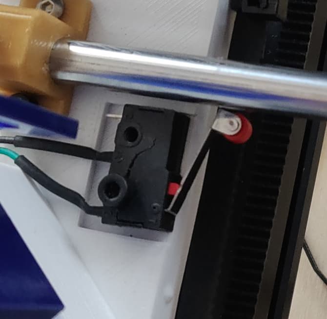
The problem was … endstops where wired as NO instead of NC… after resoldering them gantry starts to move as it sholud…
As I saw on the screenshot on reddit, the official documentation (in Chinese) want me to solder endstop as NC. I thought that they should work as NO and that caused that weird move…
In the video it sure looked like the first endstop switch was working correctly and the second endstop was not working. You should also setup your endstops the way YOU decide is best because there is a difference. Normally Open(NO) means the end stop switch and wiring is an open circuit and only a closed circuit(switch closed) will trigger the controller endstop software. A broken wire or solder joint or switch and you will NEVER sense an endstop event and your stepper motors will skip steps or worst, destroy a belt or break 3D printed parts.
Normally Closed(NC) means the endstop software will get a triggered event any time a wire is broken, switch is broken, solder comes loose, along with a switch “open” trigger.
Try it sometimes. ie run a demo gcode file and any point during the running push an endstop switch manually. You really do want to know when a wire breaks, switch breaks, solder joint fails etc before it breaks your machine.