hi.
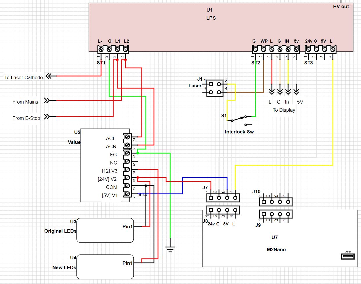
i have read as much as i can about this topic, and have learned a lot; i think i have the correct play to wire in an extra arcity 5/12/24v psu, but there are a few things i can’t confirm in my mind for certain. can y’all please check my plan? i have attached a picture
i will be putting an analog ammeter in system to keep track of mA to stock laser tube
don’s laser things implies the unit i bought is an “old” one even though i just purchased.
with the ammeter to make sure i don’t overpower, i don’t see a need to upgrade the controller or change pots at this time
questions:
to start using the second psu, i just transfer the right (blue) 5v and 24v wires to the appropriate outputs on the new psu; is that correct? i leave the grounds attached to the LPS
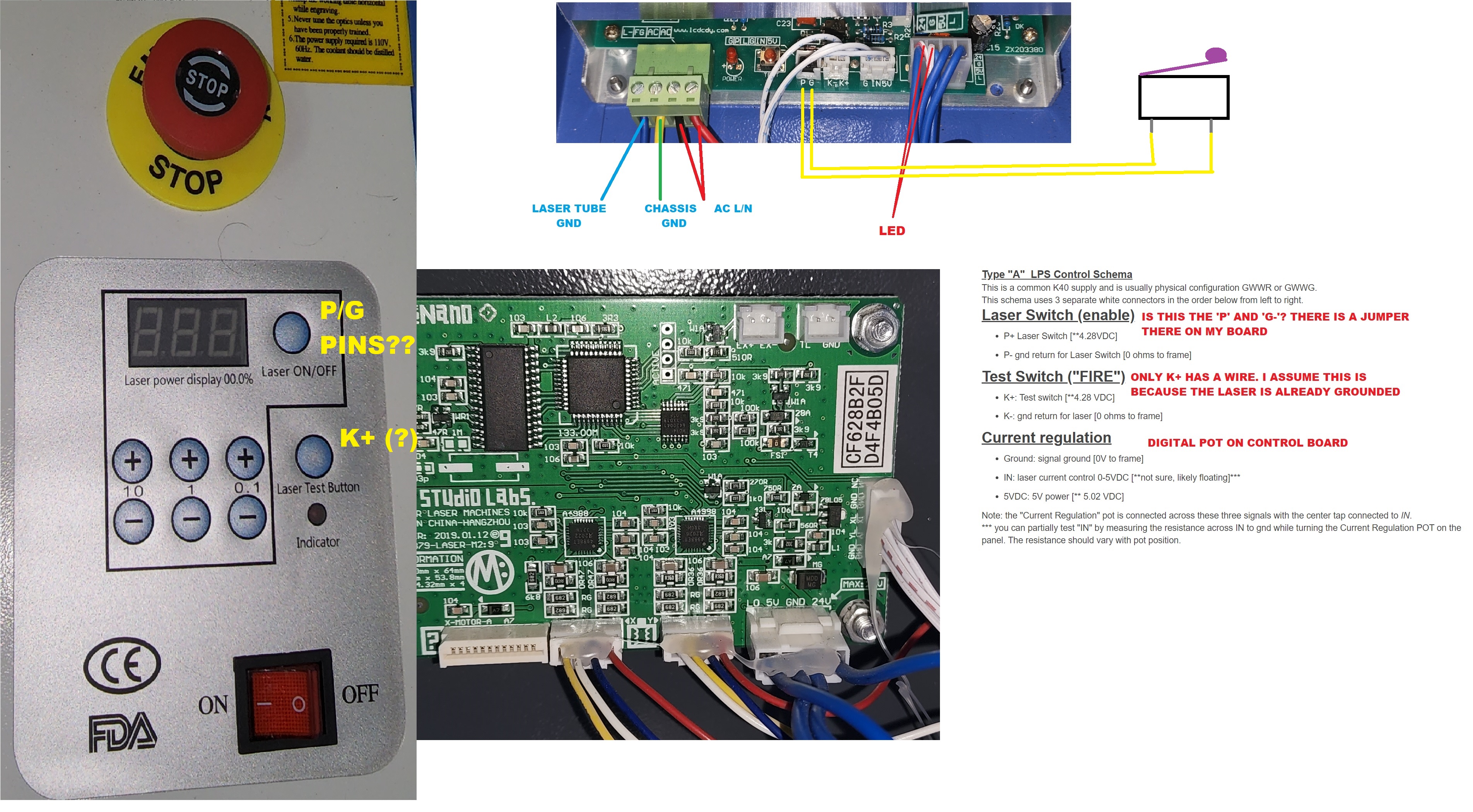
regarding K-/K+, the note i copied from don’s site implies the test button on panel uses the K+ wire; is this correct? (i meant to say the control board is already grounded, not the laser)
i installed the lid cutoff switch, but am not sure how to wire it. my deduction is the P/G plug, which is jumpered on my board (and on don’s notes is P-/P+), is part of the “enable laser” button on the panel. do i remove the jumper and put the cutoff switch interrupting the two pins? please tell me if this is a horrible deduction.
if #3 is not a correct deduction, how to i wire in the lid cutoff switch?
Your control panel doesn’t use the P (protect) pin to enable/disable the laser.
The “Laser ON/OFF” button just enables/disables the PWM signal which is used to set the power. The effect is the same: The tube doesn’t fire if the power is set to zero.
do i remove the jumper and put the cutoff switch interrupting the two pins ?
Yes. The laser is only able to fire if P is connected to G. You can connect one or more safety switches to these two pins. E.g. you can connect a lid switch and a flow switch in series to ensure that the lid is closed and the water is flowing.
Hi all, and thanks!
Dougl, i can tie the gnd from psu2 to either the “G” or “L” wire on LPS, right? I’m assuming it doesnt have to connect to both. and, a quick question. in the digikey example from another thread on this topic, they don’t seem to show the LPS and PSU2 grounds connected- the PSU2 gnd is only going to the LEDs. is this drawing not correct?
All electric circuits need to create a “loop” for the current to flow. Just as you can’t make a light bulb glow connecting only one side of a batter to the bulb and you need to “complete the circuit” by creating the loop/circuit for the electicity to flow. From the battery(+), to the light bulb, out of the light bulb and back to the battery(-).
So, if you have a power supply and you are supplying power to things like the M2Nano you not only need to connect + and - sides of the power supply to the M2Nano, the additional power supply needs to have the - side connected to what ever things the M2Nano is controlling so THAT circuit/loop exists. The M2Nano controls the laser PS(LPS) via the L signal pin on connector ST3 of the LPS. That signal needs a path back to the M2Nano and it used to be there when the LPS 24V and GND were connected to it(M2Nano). Since you cut the 24V and GND wires off the LPS and moved them to the additional Power Supply(PS) you removed the return path for the L signal circuit.
If you still have the Ground wire connecting the LPS and the M2Nano then great. It looks like ST3-G is connected to J7-2. BUT, and this is the BIG BUT, you show no connection to either the LPS or M2Nano for ground from the additional PS so it is as if you only connected one side of the battery(PS-24V and PS-5V) to the M2Nano. There is no closed circuit/loop to power the M2Nano.
You have created a circuit/loop with your LEDs but nothing else.
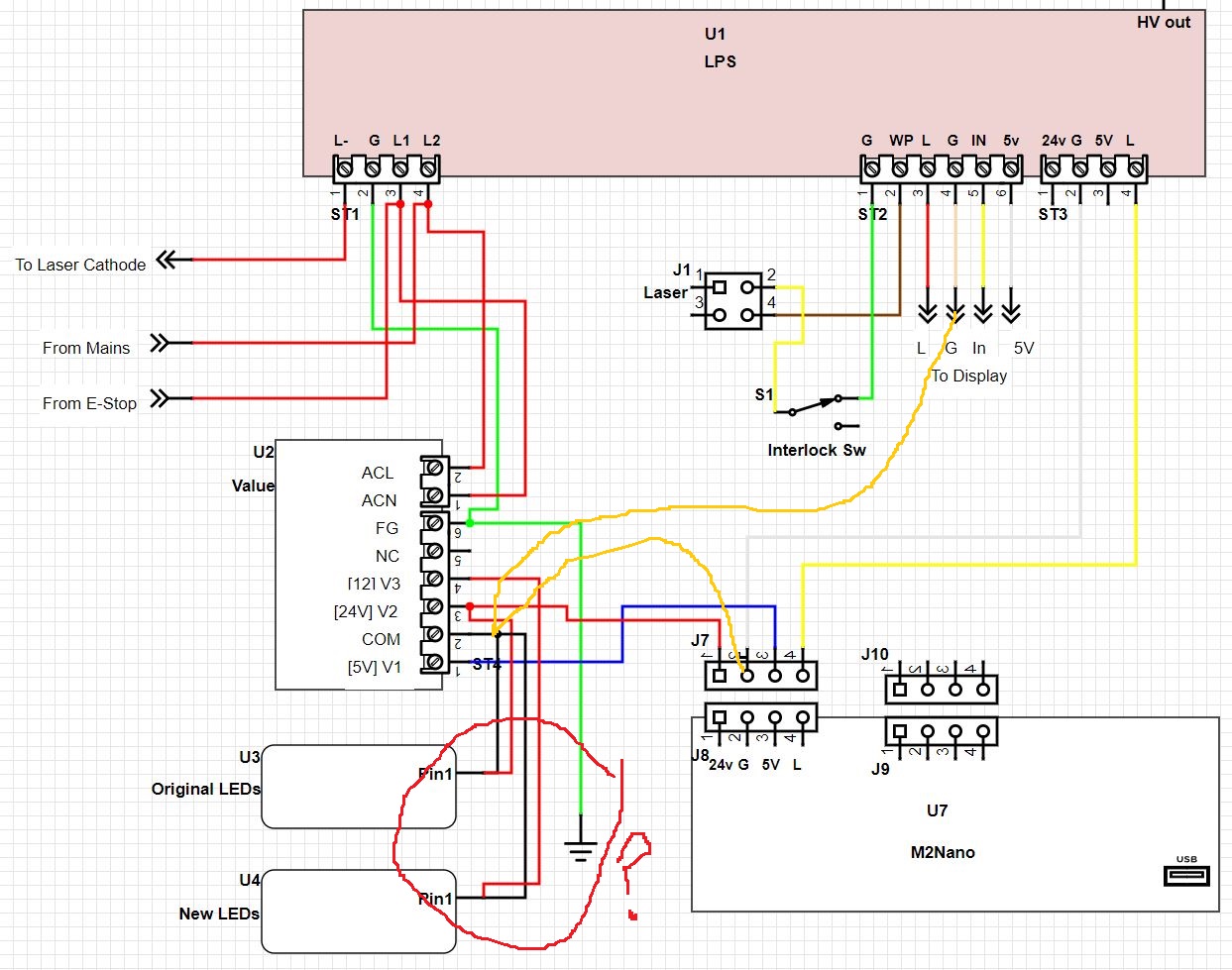
To prevent ground loops I would run a wire from each subsystems ground directly to the Power supply U2. I assume the Common and the FG are connected inside that supply.
I am not sure what the LED connections mean? It shows the 24V and Common connected to the same pin1 ?
Oh yeah, you’re right, i didn’t even notice that weird crossing on the LED Connection.
The orange drawing answered it though, as i wasn’t sure if both the G and L needed connections (apparently it’s only one of them), and i didnt know the other G (“to display” on LPS) needed to be in that group.
thanks!
The display is another electrical circuit so therefore it needs a ground along with the 5V.
I think/maybe the L signal in the display block/connector is to provide a way to fire the laser. The L signal is NOT a Ground. You’ll get a lot out of a schematic and drawing once you understand what makes up a circuit( loop ). Electricity flows in a loop if you don’t provide the complete loop things just won’t work or will go badly.
he’s not talking about how the red and black lines cross, he’s talking about a positive side of a power supply voltage being connected to the negative side of the same power supply voltage. That is called a short circuit and you DO NOT want to do that unless you really like lots of heat, melted plastic and even a failed power supply. And to top it off, no LED light or light string will illuminate if you connect both the positive and negative(ground/common) outputs from the power supply to only one of the two LED power inputs. Just more of understanding what an electrical circuit is…
So, if the gnds in the LPS are connected internally, i only need to connect to one of them then, wouldnt i? for instance, i only need your J7 orange line; the orange line to LPS “to display” is not needed.
The “to display” gnd is already connected to the 24/5 gnd internally, you’re saying. I’m confirming as its easy to tie in to the large plug wire but tougher to easily connect to the small plug wire (the display gnd).
as far as the “battery loop” example, once i make the orange J7 connection, doesn’t that also complete the loop from the PSU2 to the m2nano?
I wanted to say, i did not make that drawing, i found from another thread discussing this issue. It has a different pin/plug setup from my LPS but was close enough to ask questions from… my second post/question was whether a gnd connection was missing or not