Just wanted to share my build since it has been a little quiet. Granted what you see has been completely disassembled… After the frame was on, I put the z axis and bed, then the x and y axis only to discover that I had goofed on drilling the holes. Somehow halfway through I confused the vertical extrusions and put the 80mm hole on top instead of the bottom, resulting in not enough clearance for the x and y bars. I am pretty sure I even saw a post recently about this…
I am curious about one thing, the z axis is a PITA to align. I was able to get the whole assembly aligned and moving with the belt by hand, but I had no idea how much force is to much until I wire up the steppers. The ballscrews seem to be tight normally, so the whole thing doesn’t do, even if pushed. Should it be like this?
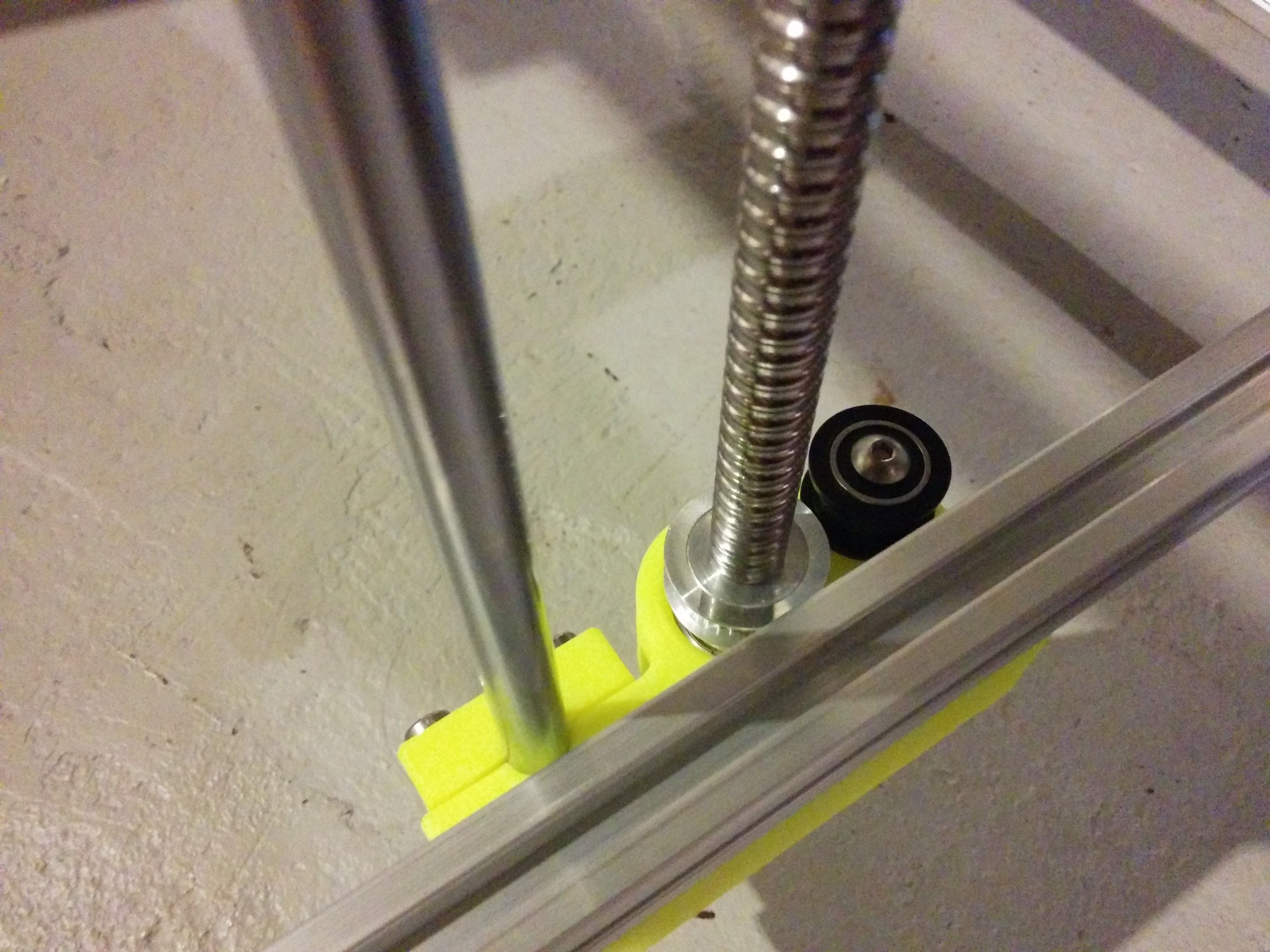
Unfortunately I cracked two of the bearing ended when installing the bearings. Polished them with a little ABS. Did the same when installing one of the bushings in the space invaders carriage. We will see how the boo-boo’s hold up.
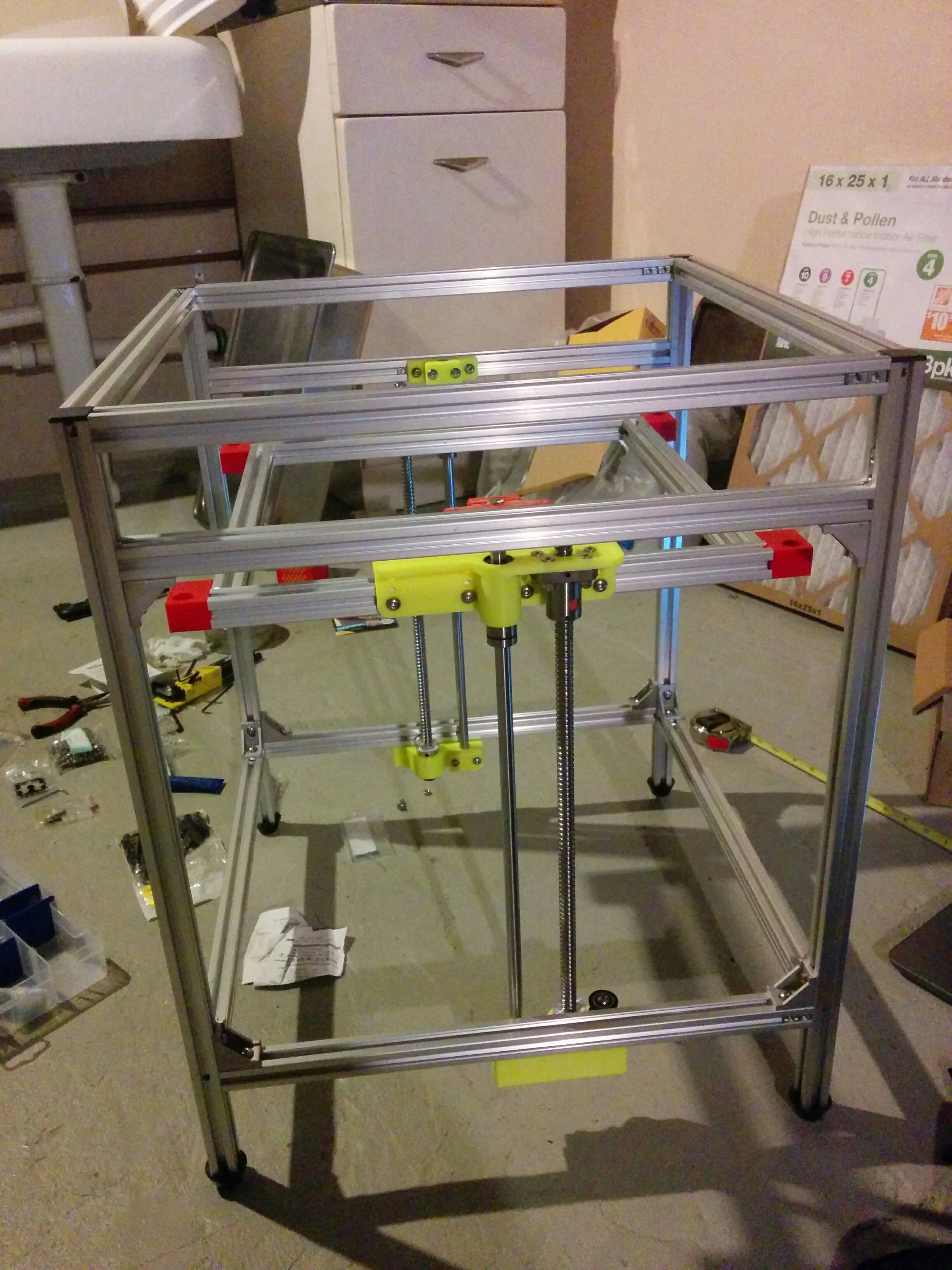
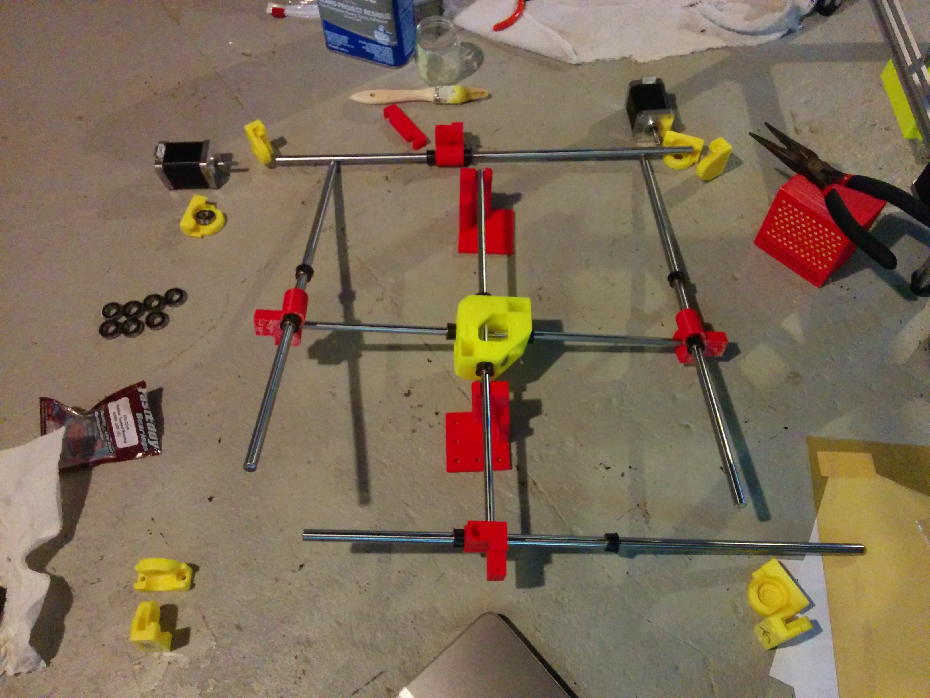
How do we use the print fixture for aligning the x and y axis? Mount them to the bed extrusions? Any pictures would be helpful. Without further adieu, the pics.
The z should move freely. Either the extrusions between the two sides of the beds are too long or Short (you did the fronts and back extrusions I see). My recommendation would be put the extrusions on the front/back not between the extrusions. Putting them between means everything must be perfect in length. Putting them front/back means you can let it find it’s own equilibrium and then tighten it down. Also there are many degrees of freedom in this build. All extrusions must be perfectly the right length. Otherwise you will bind somewhere (whether it be in the gantry or the bed).
Basically if you feel binding anywhere during the build it’s time to start measuring, squaring, traming, shiming, etc until the motion is smooth and easy. It takes a while. But as I tell people… “When it’s right you will just know”.
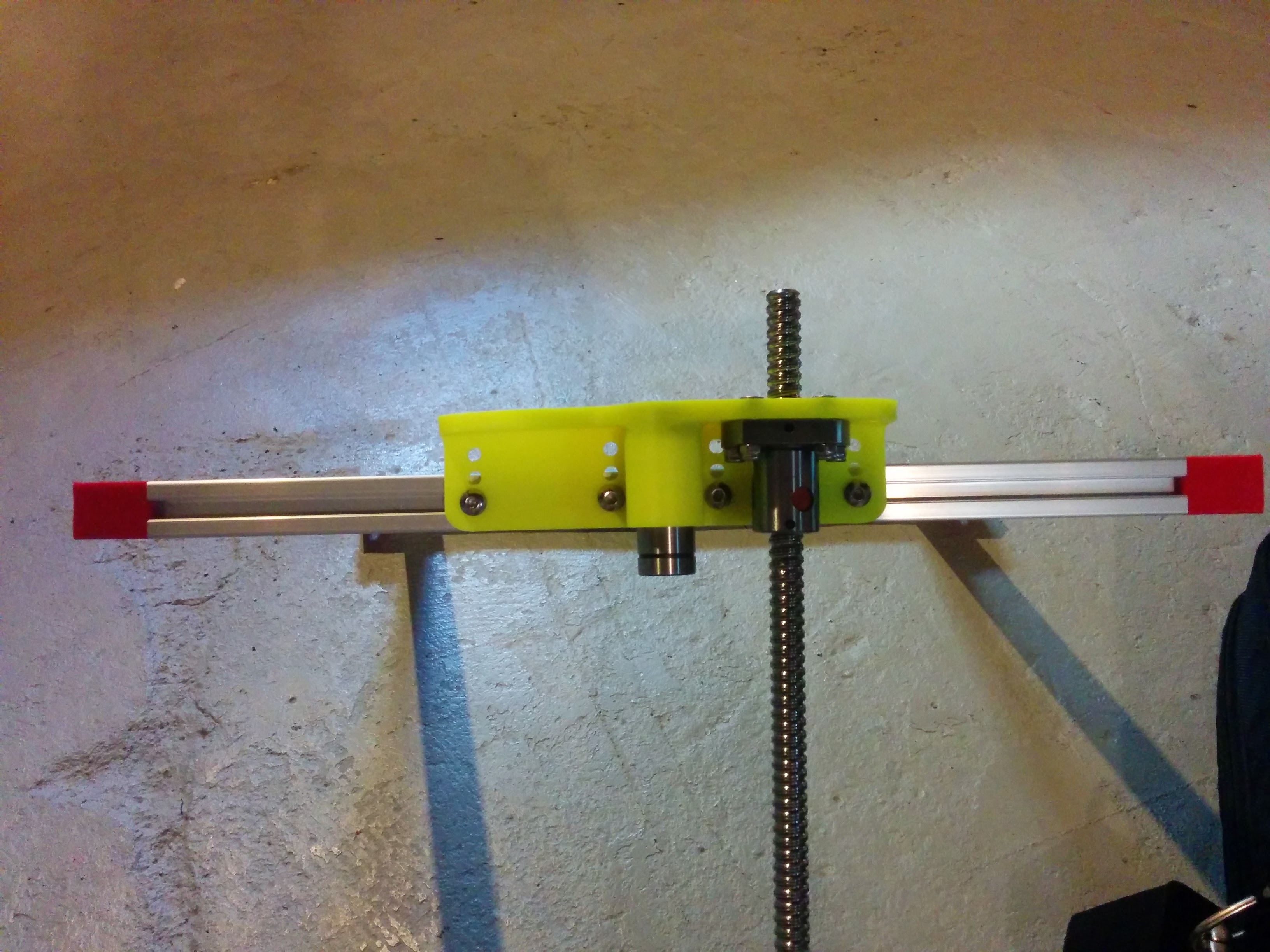
The gantry leveling guides are just to give you starting reference. Really it takes starting with a really really squared frame, with the top two side rods aligned via the guides, then moving the carriage to each corner and loosen the lower rods bearing block for that corner and let it find equilibrium. Do that for all four corners. Then move the gantry around (requires belts be installed to really get the feel). Then adjust some more.
This is the most difficult and also important part of the build. But once done, if you took your time, you should never have to mess with it again. And as the bushings break in it only gets smoother (hence the supplied break in gcode on the github).
For how to use the alignment pieces, and more tips on tuning in the frame read back through some of the old posts. There are some good ones, and some are really old now, but there are a ton of great comments back there from others who were in exactly the same spot and came out very well after tuning and some TLC.
Hi Eric, thanks for the detailed post, I am a bit confused. I guess I don’t know which is the back and which is the front. I am assuming my mistake is assembling everything for the bed first and slid that into the frame. I should put the extrusion which mounts to the z supports on, and then bring the front and back of the frame together, finishing with the two extrusions on the sides and finally the 2 bed mount extrusions (normally one on a spider v2).
Yeah they would need to be 40mm longer and the holes for the bed plate would need to be rearranged because the extrusions would be where your current mounts are. You can make what you have work for sure… but if you have binding you will need to trim or shim your current extrusions that go between the two sides to alignment. If done correctly the Z stage should be very easy movement once the belt is connected.
You should be able to unplug the stepper wiring (so you don’t push power back into the controller) and pull on the belt. Resistance should be minimal. If there is drag your are likely pulling in on the two side Z shaft & lead screws…or pushing out against them causing drag. It should move smoothly at the top and bottom (through the full range of Z motion.
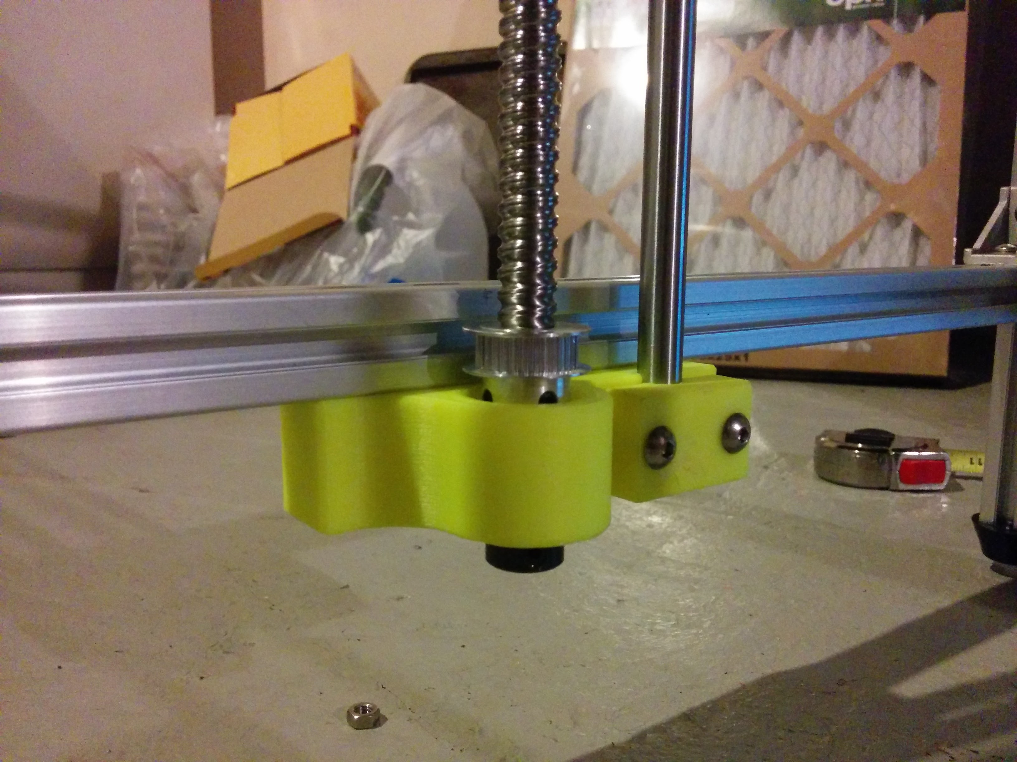
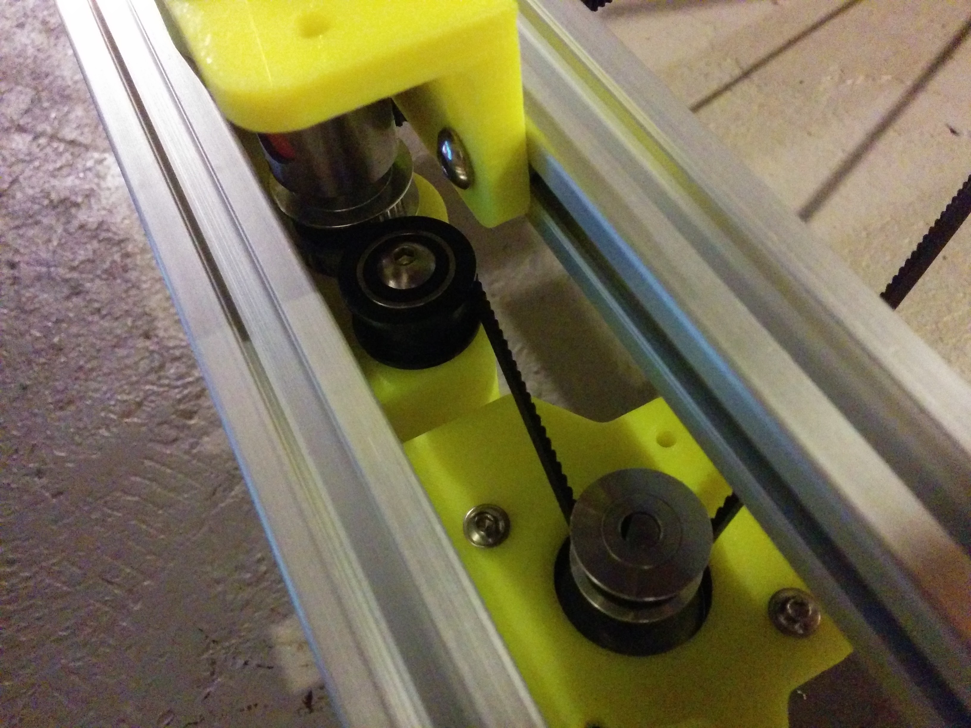
Also you don’t need the Z belt tension super tight. If you have it too tight it will likely deflect the motor mount and cause the belt to want to walk up the pulley. Then the timing belt lugs will rub on the drive pulley and lead screw pulley flanges introducing artifacts in Z.
Thanks for all the pointers. I have a better grasp as to how to assemble the frame in coordination with the x axis. Rather than rush through to start working with the fun parts of the printer I’ll slow down to make sure everything is smooth.
Hi Eric! I actually did! Your advice helped immensely. I basically disassembled the entire frame, re-drilled the holes that were in the wrong locations and reassembled everything. I went quite slowly so I haven’t gotten too far. The guys at Makeralot did an excellent job with milling everything to the correct length so everything appears to be quite square. I mounted the rods and lead screws at the mid-point of the frame first and then brought in the extrusions for the bed; I ended up leaving a little gap so there are less torsion forces on the lead screw. It appears my my printed z bed mounts are a little bit warped. I will keep an eye on everything to make sure it doesn’t cause an issue over time. Most importantly the whole assembly moves more smoothly than before (at least by hand) I still need to wire up the electronics.
The bad news is that I just discovered one of my 10 mm rods is bent. When I installed all the bits and started to move things the whole carriage basically was bouncing up and down with the rotation of the screw… I guess that’s what I get for ordering from Alie. The good news is that I already contacted the seller and they will be sending a replacement ASAP, now I will probably have to wait at least 3 weeks.
Yeah the central crossroads have a little bit more leniency but those side roads have to be “true” otherwise you’re going have an eccentric motion and that’s going to cause all sorts of problems. Glad to hear they’re rectifying the issue.