just seeing if anyone here has wired up a VFD to use the spindle enable and PWM to control the spindles speed and turning it on. (arduino uno)
I also need help wiring a relay as the coolant pin to send power to a power bar (with only a vacuum which is connected to the dust shoe.)
Cheers
Constantly use GRBL and other boards to run VFDs and SSR relays.
VFD
Controller really needs a 0-10v output to do this correctly. 0-3.3v or 0-5v has to be stepped up and can cause a large loss in a true linear ramp up.
I heard you can change the setting to accept 5v but I’ll check. I’m not too picky with the feeds so as long as I can get it within 100rpms of desired (the machines at work have 12 settings for 40-2000rpm)
Care to help with what pins go where?
Absolutely brother the below is our now forever modified for SMW3D, nothing too special, a stock unit should be similar.
Jump com to X1 feed in analog signal to com and ana1.
That’s wiring I’ll pull up the PO codes next time I’m writing a tutorial on this, expected in about a week.
You absolutely can vary input to output. Sonny (GRBL) wrote something recently for me that piece wise the the relation. This helped greatly, but till I started providing true analog 0-10, there was always a little bit of non-linear relation. +-100 will be a lot of tuning to get but I do believe it’s possible. 0-10v input this requirement is absolutely possible without much fuss.
I found the PO70 or something that changes the PWM to 5V instead of 10. Just need to figure out where the enable pin goes. Now confused even more because I see people adding FOR and REV wires but arduino doesn’t even pin out for that. I’ll post my wiring schematic soon for you to look over
If your on GRBL you don’t need to enable the direction pins. There maybe applications but I have never had the need to run a spindle backwards. I do know there are tools out there, just never had a need for them.
Great wiring diagram, I like that you recognize that the fourth wire is not needed on the spindle but may suggest running a wire to to a solid piece of metal on the spindle, it’ll help with the noise to those limits.
Get some extra .47uF caps for the limits.
You had a well set up machine if I recall correctly. What’s bringing on the change?
I plan on only going clockwise anyways.
Everything good though?
All wiring is shielded. Never had noise issues even with unshielded cable last two machines. Rather run switches as NC anyways.
Last machine sold in November. I like designing them. After this I’m making or retro fitting a mill to cnc control.
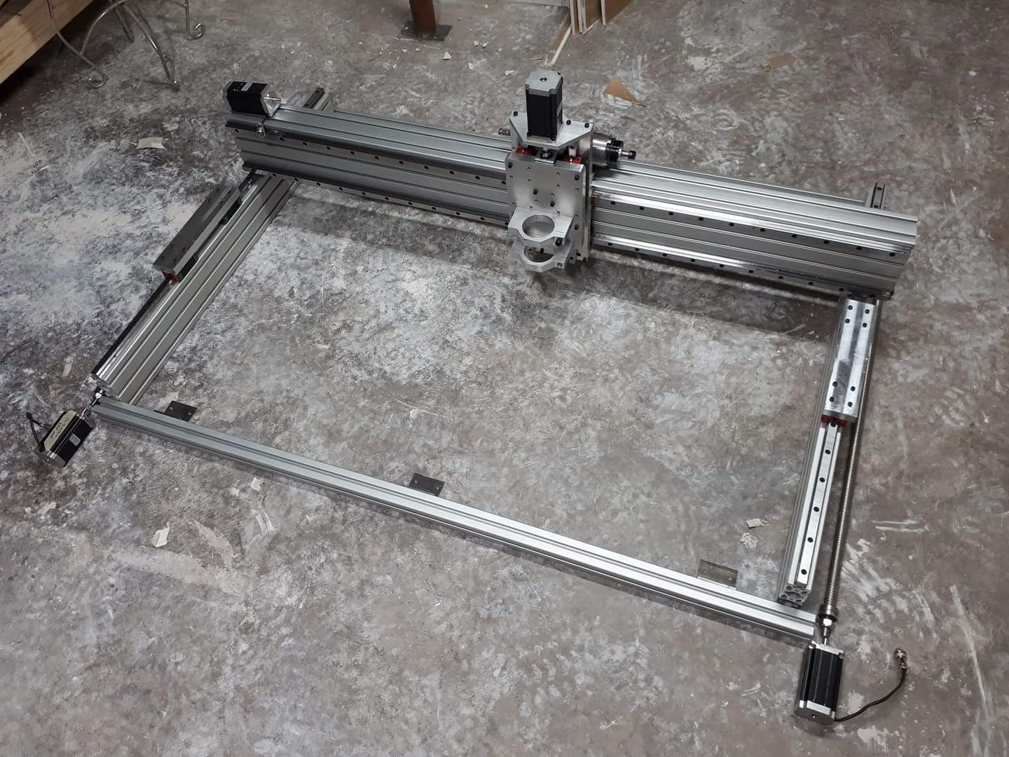
1100ipm rapids. 20mm hiwin rails. 3/4 gantry plates. 20 and 25mm ball screws. 475ozin motors.