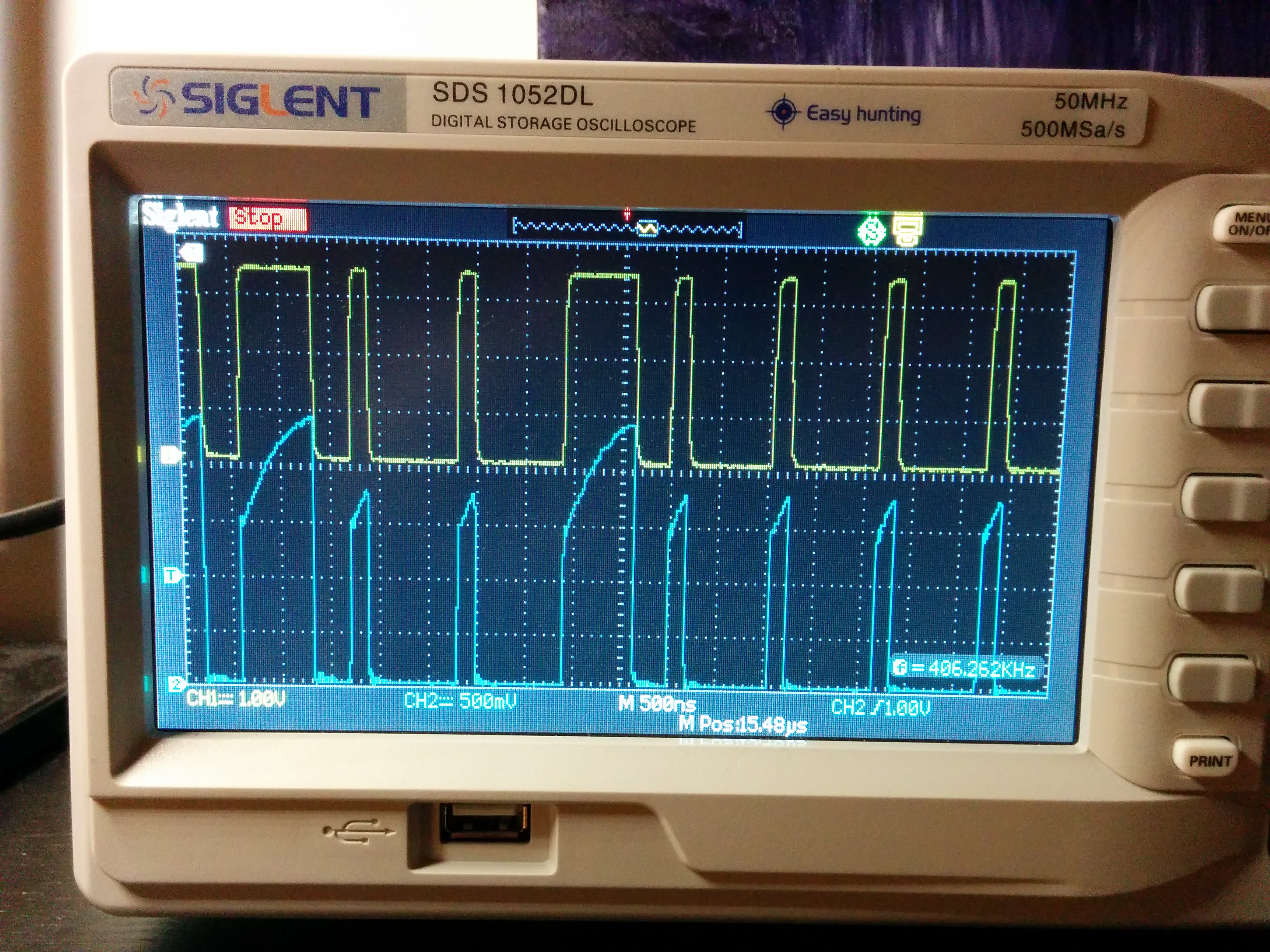
I’ve been working with a 3.3v device, STM32 blue pill, and used a logic level converter (CYT1070 I think) to bring the signaling output up to 5 volts. I kept dealing with weird flickering so set up an oscilloscope to check the output. Top signal in yellow in the image is straight off the STM32. Bottom signal is after the converter. Looks to me like the converter isn’t switching fast enough. What are peoples’ “goto” solution for handling 3.3v devices?
For almost all applications, I’ve been able to drive WS2812b pixels directly from 3.3v
That started to become unreliable when I started getting into using parallel output in general, which you’ll need to keep frame rate smooth for anything over 300-400 pixels.
When I started getting lots of flicker, I used a SN74HCT chip as a converter to step up to 5 volts, and that worked fine
There are some other little hacks you can do as well: Use a diode to drop the Vcc voltage of ONLY the first LED in your strip to 4.3 v, etc etc.
Here are two great posts to help understand the workings of the LEDs:
The 74HCT245 works great.

@Jason_Coon (or others), do I remember you’ve had success with a different chip that was slightly smaller then the 74HCT245? And if so what pixels where you using?
@marmil Yeah, I have successfully used the slightly smaller SN74HCT125N, which is 14 pin instead of the 245’s 20 pins. 14 pin is the smallest I’ve been able to find in through hole mount. I think any chip in the 74HCT or 74AHCT families might work, but have tested only those two. I’ve tested with WS2811, WS2812, APA102.
Yup, that waveform looks like one of those mosfet+resistors level shifters.
Years ago Adafruit & Sparkfun promoted them as useful for all your level shifting needs. It was a great sales pitch & a seductive idea… just keep a few of these cheap boards in your toolkit and use them whenever you need to convert a signal between 2 voltages.
Turns out, that’s pretty terrible technical advice. These level shifters really only work for “open collector” protocols like I2C. They have slow rise time, which is terrible for anything high speed. Worse yet, they have much faster fall time, which means horrible distortion of waveforms like PWM and WS2811 / WS2812B signals.
Adafruit did add a footnote about these level shifters not being the fastest. They did start stocking other unidirectional ones. Sparkfun also revised their sales pitch somewhat. But the seductive idea, that you can just put this conveniently little circuit between any digital output & input when you need the signal level changed has really stuck. Many people still believe they’re good for all or most applications. Truth is, they’re really only good for I2C and other open collector protocols. They’re poor for almost everything else.
i fell for that terrible technical advice. Wondered why my chit was sucking. Later, I found the revised text from Adafruit. Much cursing ensued.
I have used the FET trick using some small 2N7002’s. https://electronics.stackexchange.com/questions/105218/3v3-to-5v-level-conversion
Yup, that’s the bad circuit right there! DO NOT use it for addressable LEDs.
I have successfully used the TC4427 (dual high-speed MOSFET driver) in Christmas light displays where the distance from the processor (ESP8266) to the first LED was > 2m. I run the LEDs off of the 5V supply and the TC4427 swings nicely to that rail. They are cheap, compact and easy to use. Somewhere I have some oscilloscope photos I took…
@Jeff_Mizener I like that small size. Was there anything extra needed with the wiring, or just inputs, outputs, and the pos/neg connections?
@marmil This is what I use. I bought a bunch of the dual non-inverting ones and they work just fine for most of the things where I need one or two lines driven or level-shifted. I like that they are available in a dip-8 package too.
missing/deleted image from Google+
Co-incidentally I just posted about what I do above. Check out my solution at: https://www.youtube.com/channel/UCkomrWJWXxF2rSE4lJ8KrKA
Works perfectly for me, costs almost nothing, is super simple, and totally reliable.
@LED_Head I left a comment and ThumbsUp on the video. Interesting idea. If you have any other peripherals for the ESP besides just the LEDs, you’ll need to ensure that they use your derived zero instead of the PS zero rail as the references (switches, etc). This is nice also because in it’s simplest form, you save yourself a voltage regulator to derive the 3.3v from a 5v LED supply. If the diodes are of the same type and not too dodgy, the delta between derived + and 0v will move up and down together as the load on the power source changes. A nice bypassed electrolytic across the ESP power input mitigates that as well.