Hello, I’ll show you first the video with the alignment, it’s better than any word I can say:
I did the 1st mirror alignment first and it’s ok, but now when I test the 2nd it it’s fine with the header at 3 corners, but not at the upper right corner of the bed. I find no sense on this, at least with the mirror alignment issue, I think this could be another problem, maybe one of the bridge slides is not aligned and the whole bridge is rotating while it moves?
Might watch this video on the perfect alignment by Russ Sadler… almost at the end he addresses the 4th corner issue… The whole video is good, but if you skip out to almost the end at 33:10 he speaks about the issue.
You might do better is you make the burn brown instead of burnt, that way it won’t obliterate the previous mark … lower the power or shorten the pulse.
next day:
Wow, this man explains everything so well that I’m enjoying the video, even paying attention to things I already know.
EDIT:
Today I found this fact about the bridge level:
When I thought I knew the problem, it turns out that is happening the contrary.
I took the level tool to see how was it going with the bridge at the front and the rear rails ends.
My guess before this was that the right hand rail was a little down on the rear end compared with the left hand one, according with the beam target seen in the first video, but it turns out to be the opposite of this.
I already saw that video.I think what you mentioned about minute 33 of the video is not my problem. He says about aligning the back left hand corner with the front right hand corner spots. In my case those two spots are well aligned, the problem is just the back right hand corner.
I thought it could be the rails not perfectly leveled on the back ends but I think it’s not that, because, they are not at level, but the back right hand rail end is higher than the left hand one, so the spot there should be under the others, but it’s the contrary, I don’t understand why. I shown it in my previous reply.
I’ve realized about something:
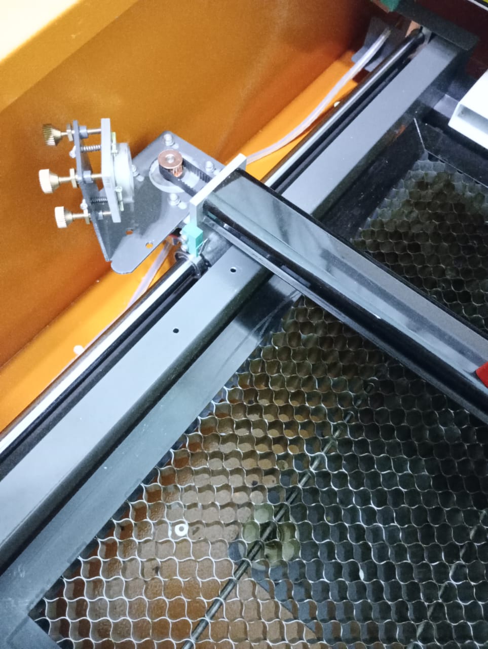
The 2nd mirror is attached to the bridge, so when the bridge rotate due to the rails bad leveling, the mirror also rotate with it.
So it would seem your right rear corner of the frame is too high. That’s a bit of a pain since if it were too low then a shim could bring it back to level. Now it seems your option is to put equal shims under the other 3 corners to bring them inline with the 4th corner.
Or is there a way to lower that forth corner on your machine? is your table flat and level?
I don’t really know if it’s possible to lower that 4th corner, the attachment of the rail to the frame is impossible to see clearly as the chassis is hiding it, I’ll need to unmount the whole structure and do the leveling outside of the chassis.
Wish me good luck guys… T.T
it looks like there’s some place to adjust it.
I think I found a way to adjust it without unmounting the frame O.o
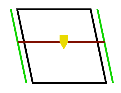
There is a chance that my structure is twisted like this:
Could that be the cause of the problem?
I don’t see how, because of as long as the laser beam from mirror 1 is parallel to the Y axis(green) and the laser beam from mirror 2 is parallel to the X axis (red), it should work fine. Am I wrong?
So you moved the end of your bearing rod at the right rear corner down so that when you put the bubble level on the X axis/gantry it now shows level(as before) at the front AND level in the back but your still getting ONLY a high laser spot on the right rear corner?
That is very odd.
Having the frame in a parallelogram like you just pictured doesn’t change anything regarding mirrors if things are parallel. It would be another problem(not marking a square when design is a square).
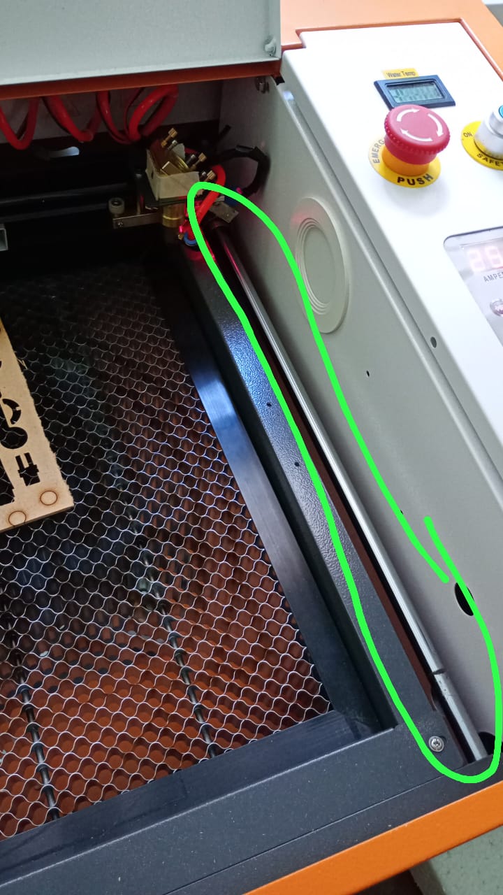
Yes, I moved the end of the bearing rod at the right rear corner down. Now the gantry is in level all along the way. The problem persist. But I have made another detection: the beam spot isn’t the same in the middle way between front right corner and back right corner, it’s lower there than in the two corners:
Then your rod(right side) is bent. You should be able to put a straight edge on the rod to tell if it’s bent. or you can spin it 180 deg and see if now it goes high in the middle position instead of low.
I tried spinning 180º the right Y rail, and then spinning 180º the left rail, both times the spot hits the same place than beofre. So rails are straight. Now, if the gantry were the problem, the spot should be the same if I place the head on the right side of the gantry and leave it there. But even with the head static in that X position the spot fails the alignment when I move along the Y axis. I don’t know what else could it be.
The weird thing is the bad alignment starts from the center of the rail to the back, it is not going gradually from the front to the back. I mean, when I place the head at the front right corner, it’s aligned, when I move it to the middle right it stills being ok, and from there to the back it gradually misaligns. I thought that was only possible with a bent rail but spinning the rails 180º does the same fail.
Could it be the belts? maybe one is tighter than the other? or some magnetic force bending the laser beam?
Enough… I’m going to make 3 holes in the machine chassis to adjust the rails easily