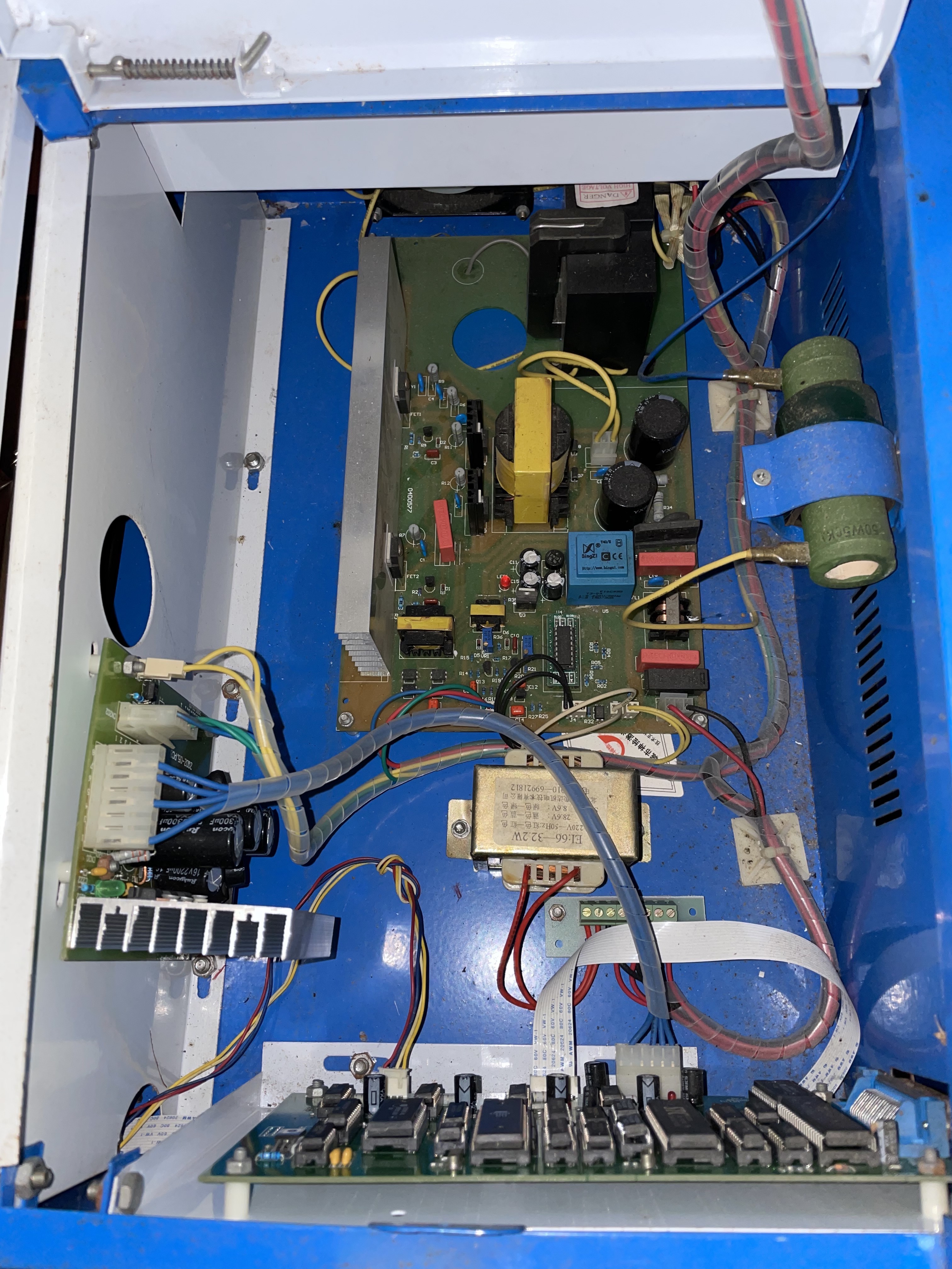
It has finally allowed me to upload a photo. (Main board)
I have searched for a moshi board but none appear to be the same as what I have.
It has finally allowed me to upload a photo. (Main board)
I have searched for a moshi board but none appear to be the same as what I have.
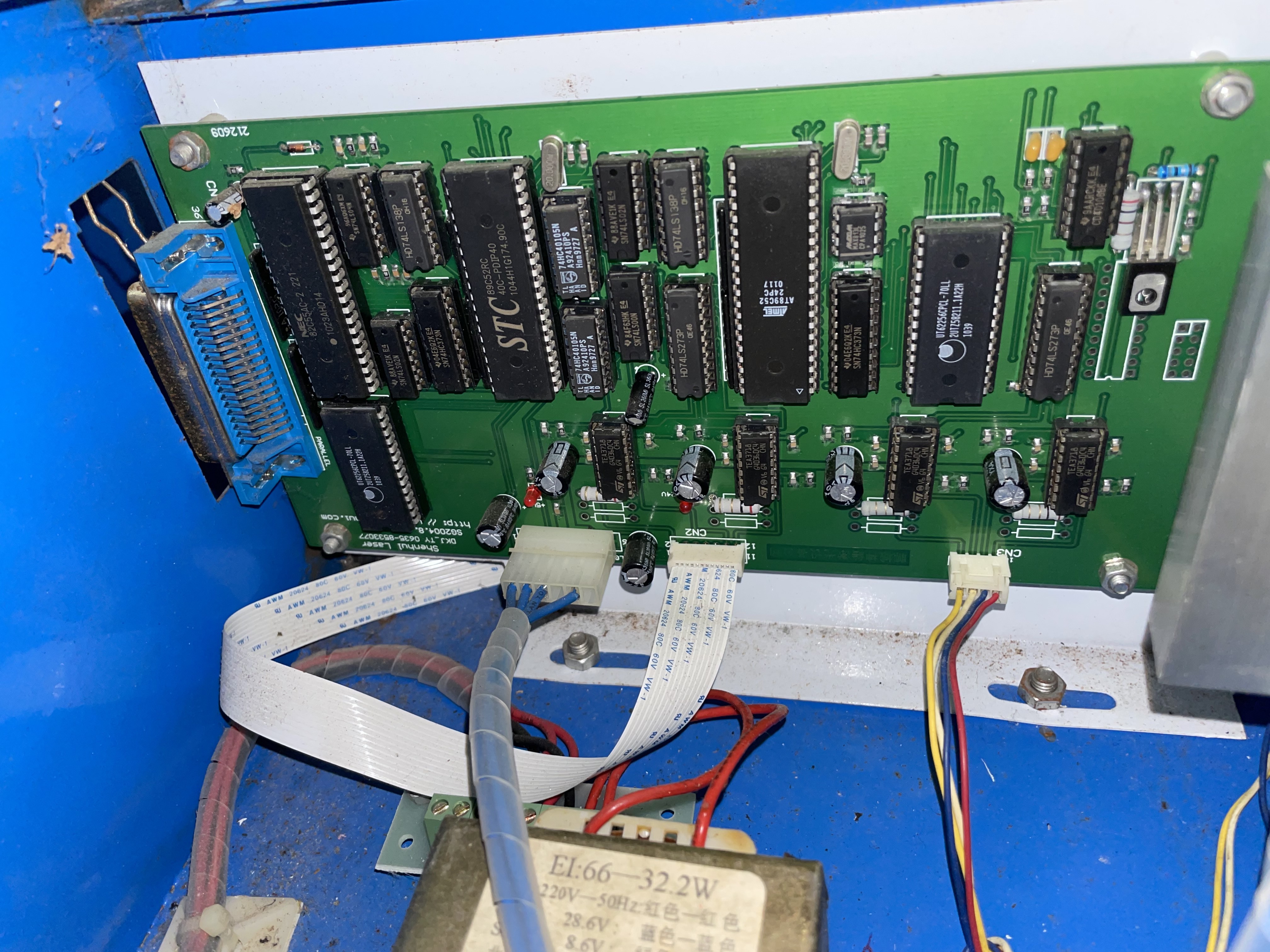
The text in the bottom left corner might provide a clue.
It looks ancient. The parallel port is definitely inconvenient.
Well, the good news is that the connectors do look almost the same as recent ones. The one on the right should be for the Y motor. The 12-pin FFC should be for the X motor and the endstops. The 6-pin connector on the left which only uses 4 wires has to be changed to a 4-pin one and then it should work with an M2 (or M3) Nano or any of the K40 upgrade controllers which got a connector for that 12-pin flexible flat cable.
The bad news is that your machine does use that 12-pin flexible flat cable, which is inconvenient if you want to use some controller which does not happen to have a connector for it. None of the DSP controllers have one, for example.
If you want to use one of those controllers, you either have to use some kind of adapter/breakout board or redo the wiring for the X motor and the endstops.
Here is @kwUK 's other photo, just so it’s inline with the rest of the thread.
They’ve done a lot to streamline the newer K40s, or at least hidden a lot of components under the cover for the laser PSU…
2004 Shenhul laser, by the marking on the board.
Even if you could reverse engineer that it has a parallel port which is impossible. You can swap that board out for probably an M3 Nano for USD$25 or so. The ribbon x, standard stepper y stuff is still the same today. In theory most of that stuff looks properly adaptable for modern lasers. You could probably buy a few different gcode controller cards for it. The thing that matters are the connections You need to fire the laser and control the stepper motors. You probably can’t get a computer with an old parallel port for cheaper than you could get a newer card with a usb port.
I’ve have been given a known good M2 NANO board.
What would I need to do to get this wired in working?
What software would I then need to use?
From the K40 Intro at the top of each page here:
M2 Nano: Lowest cost, driven by K40 Whisperer , Meerk40t , or VisiCut open source options, or the generally inferior proprietary software shipped with the unit. Cannot be driven by Lightburn directly; MeerK40t can translate between Lightburn and the M2 Nano.
There’s lots of valuable information in the Getting Started with CO2 Lasers category that the intro is in. ![]()
Think I may sell that unit then as no real use to me.
Thanks for all the help everyone, appreciate it.
If it has a TEST button on the front/top panel and you can manually cut 3mm baltic birch plywood in one pass manually moving the laser head slowly from left to right then mention that in your sales pitch. It identifies that the HV power supply and laser tube is working. But only do that with distilled water circulating through the tube. Running it without water moving will quickly kill the tube.
Otherwise you’d be selling a chassis needing a new tube, LPS and controller so maybe worth US$100 to the right person. US$0.02
Hi Dougl, Yes I have had it running and pushing the laser head slowly with my hand for testing that it was all working fine, had to get a pump for it and water so I didn’t damage anything as I have a larger laser that I use.
Just a shame for me that it has the parallel port and wont be easy for me to change to another board to use Lightburn which I am still learning to use, much better than RDWorks which I was originally recommended to use.
Will make sure to advise in listing that it is all working and cuts well.
Looking online they are listing around £300
I’d try something like this first…
Seems cheap, lots of variants…
![]()
But his old board has 2 Atmel 8bit microcontrollers so what is going on on the parallel port is likely not just a serial stream.
It wouldn’t take much to rewire it to work with a standard Smoothieware compatible board if skilled in a bit of soldering, wire crimping and ohming out things with a multi-meter. But as it is with a parallel port for input to control it, who knows what pins were doing what and what software was used to wiggle those parallel port pins.
Or a data stream!
In general, the parallel port was also basically the GPIO header, and the USB/parallel port adapters are specific to printers. They are extremely unlikely to work for any other application of the parallel port.
(I did much of the early work on the Linux parallel port driver so I have some understanding of the difference between using it for a printer and using it as a kind of GPIO.)
What would it be?
These 8 bit machines are plenty fast for most printers.
Seems like many of these they handle like a printer… Wonder if they have a specific driver for it…
![]()
they were often used as GPIO pins wiggling independent pins. For example CNCs had step/direction pin pairs for 3 axis plus an enable pin and inputs for endstops and e-stop.
I put an Arduino running GRBL on the parallel port of a CNC I have and that turned it into a USB compatible system. Something like this could be done with the machine in question if we knew what the parallel port signal names were.
Rather than trying to resurrect this connection logic, converting to one of the current controllers would seem to be a better use of time… its not that difficult ![]()
You are probably correct, but $<20 I’d try it and see what happened… it’s relatively low cost and if it’s a normal parallel port, you might have success…
I still follow the KISS principle… low cost to check… could be a total loss of 20 bucks or it could work …
It would still be worth having the machine, even if you had to gut the electronics…
![]()
Speaking again as someone who has written and maintained a parallel port driver, it looks like a waste of time and $20.
That’s very possible…
![]()
So you think that I should install the M2 NANO board I have spare?
Current plug has 5 ports and M2 has 4 so I would need to change the plug, how would I know which wire goes where?
I really like tinkering but unsure on what exactly I need to do here to get this unit up and running. If I need to use different software that’s not a problem as that is easily sorted out.
Thank you all for your input, appreciate it.
That would be the least costly option.
If I were you I would:
First draw a schematic of what you have including enumerating what voltages are present on supply connections. You can use the schematic I provided below as a starting point. Use a DVM to make voltage and continuity measurements. This painstaking activity will save you a lot of grief as you start the conversion.
Then post it here and we can review it.
Draw up another schematic adding the M2. Show remove/Add wiring.
Rewire and start testing one subsystem at a time. We can give you suggestions on how to test when you get to this point.
Here is a schematic of my machine when it was nearly stock. This will not be the same as yours but will give you some context of how K40’s were wired.
Scheme-it-export-K40-wiring-2023-11-12-11-22.pdf (628.3 KB)
To provide you with some scope, you would have to sort out as a min. these systems:
The DC power to the M2:
Looks like there is a separate supply on the left sidewall.
Convert the power connector on the current board to a 4-pin that matches the M2
X & Y Axis stepper and endstop connections
The white ribbon cable (CN2) looks compatible as does the CN3 cable.
Verify connections with ohm meter.
Control Panel Connections
Don’t know what the current panel is, post picture
Create a schematic of the power pot, test switch etc.
Connections between the LPS and the M2
L control
AC connections
To control panel
To LPS and DC supplies