ESP32-S DEV Board – Rev 2.0
A few months ago, I started to work on an ESP32-S SOC module in Arduino Uno form factor. This is Revision 2.0 – the ESP32-S Dev Board – Rev 2.0
During the time since I designed, and ultimately had the Rev 1.0 PCB manufactured, It has quickly become one of my go-to development platforms, something that I hoped it would become. It also seemed to be gaining popularity online, with quite a few of them being ordered.
Problems did however arise, as the manufacturer discontinued the SOC module, the AI-Thinker ESP32-S, but, as this was based on the ESP32 WROOM32 from Espressif, which, while still old, was still in production, it was not a serious problem.
Using the Rev 1.0 device was easy enough, but I soon started to experience some irritation, as in my attempts to build a very streamlined device, I left out some add-on components, that now seemed to be a very good idea to have on board…
Let me explain:
In the initial design, I did not include a DC barrel connector, as well as no USB port with a USB-to-serial converter, my argument being that the USB port is usually only used a few times, or at most once, as I usually upload firmware to ESP32’s OTA. Power ( on the bench that is, is usually supplied via a pair of wires, so no dedicated connector seemed to be necessary.
As I proceeded to design addon shields for the device, it became clear that that power connector, at minimum, as well as the standard 2-transistor reset/flash circuit, would be a very very welcome addition to this PCB.
See the pictures below for a comparison of the two boards…
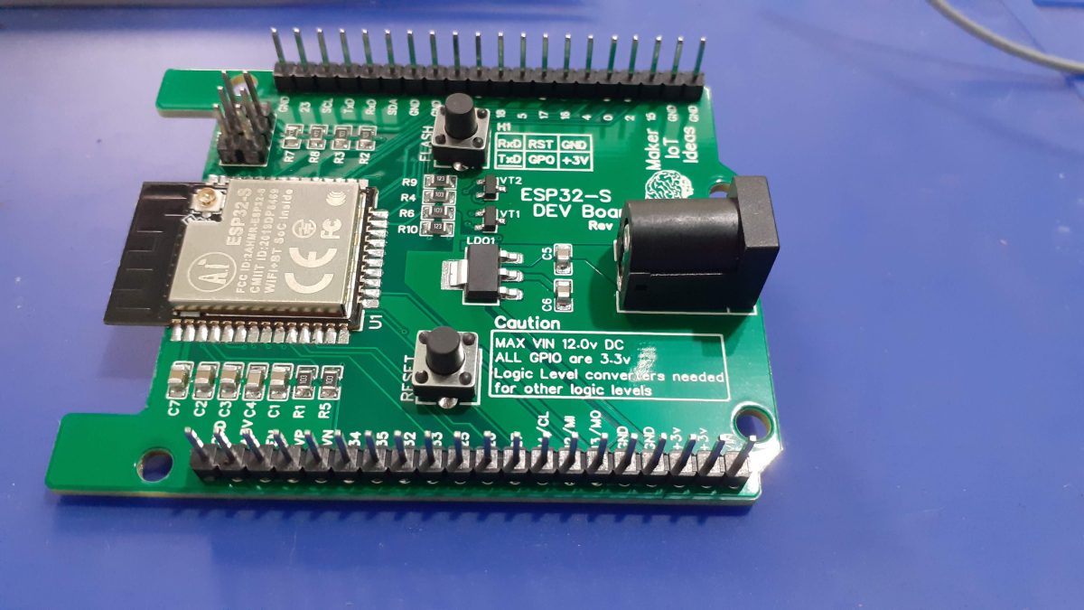
ESP32-S Dev Board Rev 1.0

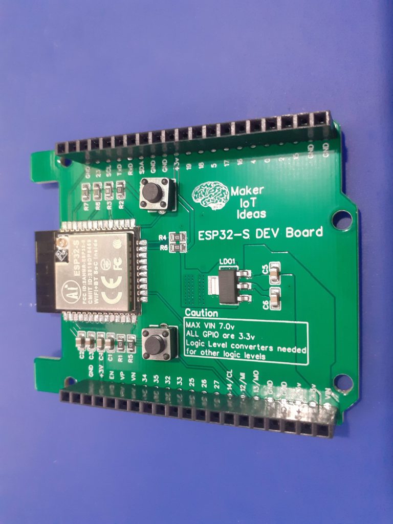
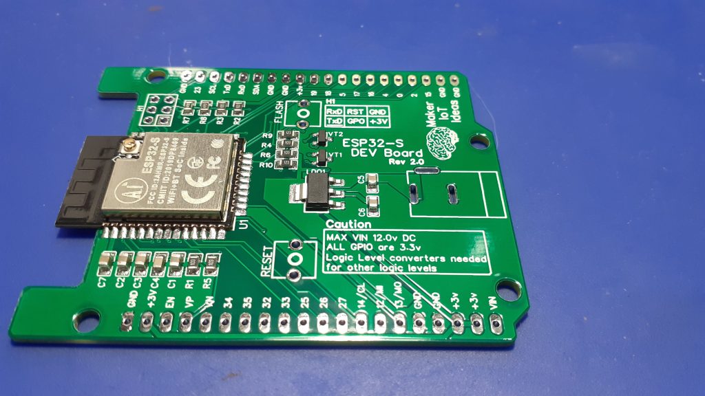
ESP32-S Dev Board Rev 2.0
I have also decided to use male header pins on this build, as I sort of like to use them more than the female ones ( which seem to develop connectivity issues after a while – this could be due to the quality of the connector strips that I bought)
What changed, and how?
I made quite a few changes, most of them quite subtle.
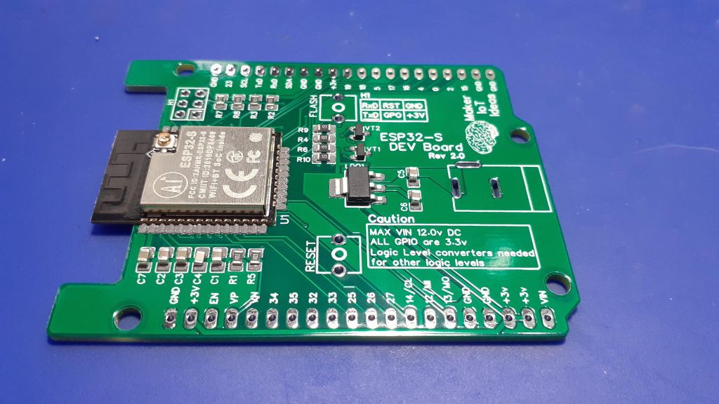
The most obvious would be the addition of a DC Barrel connector, to allow the device to be powered easier when used as a permanent project. In addition to this, a 6-pin programming header was added, in order to make flashing the device with an external USB-to-serial adapter easier than usual. ( This means that the standard 2-transistor reset/flash circuit was also added). That meant a slight increase in the component count. Additional decoupling capacitors were also added to add voltage stability to the ESP32-S. The routing of the entire board was also changed, with more attention being paid to the heat dissipation of the ESP32-S module, which tended to get a bit hot.
Power is provided by a 3.3v LDO regulator, the same as in the Rev 1.0 hardware.
I do plan to change this to a small buck converter in the near future, as the 800mA provided by the LDO regulator can get a bit limited, especially when using I2S Audio devices, something which I am doing quite a lot over the last few months.
Manufacturing
The PCB for this project was sponsored by PCBWay.
Disclaimer:
Clicking on the PCBWay link will take you to the PCBWay website. It will enable you to get a $5.00 USD voucher towards your first PCB order. (Only if you sign up for a free account).
I shall also receive a 10% commission AT NO COST to you if, and only if, a paid order is generated from the click on this link.
Assembly
This PCB will definitely benefit from using a stencil, but it is not strictly necessary. I did however get one, as I prefer the uniform solder-paste application and speed that they give me.
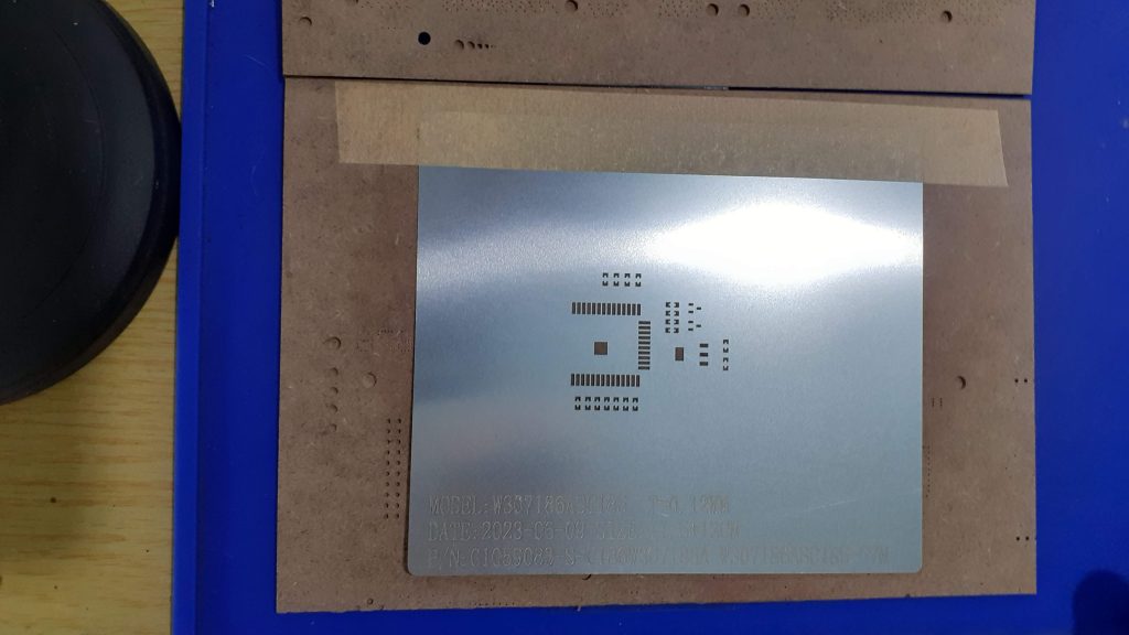
Stencil for SMD assembly
Component placing took only about 10 minutes in total, including the time needed to place and use the stencil, apply solder paste, select components and place them in their correct positions.
After Solder paste application – Before reflow soldering
The board was then reflow soldered on a hotplate at 223 degrees Centigrade.
After Reflow soldering
The board was inspected for solder bridges and bad joints, and I then proceeded with through-hole component assembly, which took about another 10 minutes.
The completed PCB
Conclusion
This was definitely a very worthwhile revision on a very useful piece of equipment. The addition of the programming header, in particular, already saves quite a bit of time, and the DC Barrel connector opens up new possibilities for the use of the device outside of the “bench” environment.