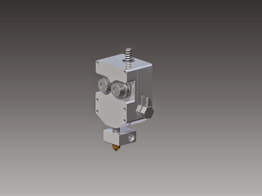
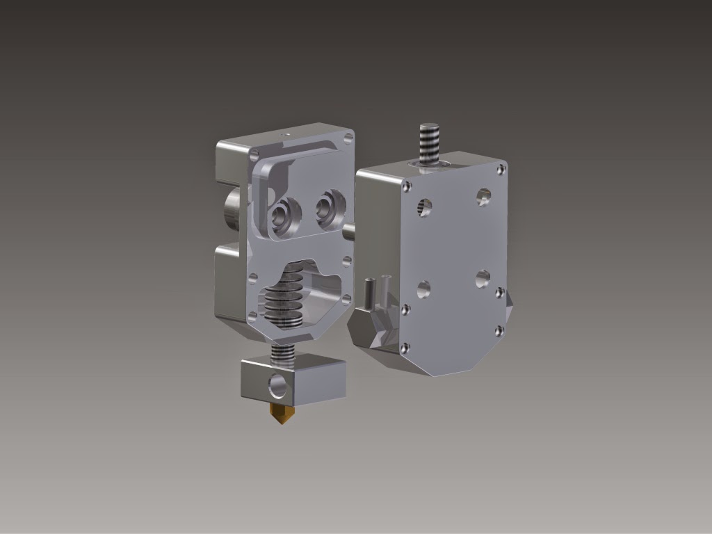
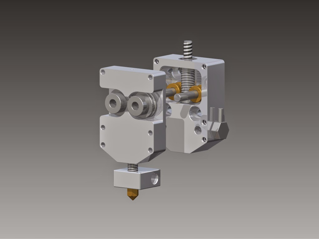
I Designed new extruder for my H-Bot build. It have watercooling and dual extruder pulleys like Printbot Gear Head extruder! It’s flexible driveshaft driven and have 1:25 gear ratio via worm gear. (extruder pulleys have od 16mm)
Heatbreak will be stainless steel with 2mm bore and it’ll have heat sink itself. So there is no PFTE tube or anything inside it, only metal. There is still many places with too much material left, but for now software says it weights 192 gramms(+water and bolts)
It would be nice to hear some ideas about this! Should I put O-ring groove around water space or something?
That will leak without some kind of sealing. If your water pressure is low enough, you might be able to use a silicone sealant (Permatex is a popular brand) instead of adding an o-ring groove around the chamber. Adding an o-ring would be the safe way to go though.
I thought I put silicone sealant to it since there wouldn’t be strong pressure. But maybe I will put O-ring there. I just need to make thicker walls to it!
I might remove those lower M5 bolt holes. It will stay rigidly in place with only two bolts. So I can get it even smaller and more room for O-ring groove.
Absolutely interesting design. I have a few concerns however.
How does the heatsink/heat break thread into the metal part? Further how are you sealing this point of entry?
I don’t think it’s necessary to have the finned portions of the heatsink inside the shroud. The aluminum body will act as more than good enough thermal transfer area. I would personally suggest a design similar to kraken where the filament path is completely separated from the water path.
I do Mechanical design for a living with SolidWorks, let me know if you’d like help collaborating. Definitely appreciate where you’re going with this!
@Matt_Olsen1 yep, I figured out that also and already started to design groove for O-ring. I need though find suitable o-ring first so I can ensure that there is replacement ready for it if needed. Main reason is shorter melt zone and overall better cooling. I can also design it smaller and hopefully lighter. And it’s very nice looking @Mike_Kelly_Mike_Make Heatsink and heat break is one solid part and it is threaded. Closer to gears, it will have o-ring pressed between heat break and aluminum and below the aluminum body I thought to put copper gasket/washer under nut.
Okay, that’s probably true, it will give enough heat without finned portions but I think they don’t disturb there? Since it doesn’t suffer mechanically stress.
Is the sealing only reason why you would suggest kraken style solution, or is there something else in your mind?
Thanks for your offer to help! Even this helps a lot, when people discuss with me!
@Topias_Korpi In general it’s advisable to minimize the number of connections on watertight pieces of equipment. The more connection points you have the higher your chances of leakage. If you could minimize it down to 3 seal poinnts (2 fittings + face) I think you’d have a better design.
It looks to me like your heatbreak/heatsink combo has a change in thread size? I also don’t like the idea of having a gasket on the heat break because of the elevated temperatures. This whole thing could be avoided by integrating the heatsink into the body and using a separate heatbreak.
This is designed to me machined on a CNC mill. It seems like it would have quite a lot of flow resistance so many it only needs 2-3 channels instead of how many I put it. Really feels like overkill but a CNC wouldn’t really care if you have a strong enough pump.
I think the dual wheel pincher approach is a little questionable and am waiting for more feedback from the testers. I think the old style of using a bearing on a spring is fine. I also think for flexible filaments you want a PTFE liner. I would go with an M7 tap on the bottom and use a E3Dv6 heatbreak with a PTFE tube run through it.
Yes, there is 10mm thread to aluminum block and 6mm thread to heater element. I designed it to 10mm only for having more surface to give heat(which feels unnecessary for now).
I will design the heat break again(6mm threaded plug as usual) , and make it go separate from water channel. I’m making this with 3 axis lathe with power tools so I’m going to mill same kind of flanges inside it, as you have in your demonstration. This will again make whole thing little shorter and lighter also!
What do you think about to making heat break with better heat conducting material? Even it literally is heat break and stainless steel is used for a reason, but since it is actively cooled, I think melt zone would be even shorter if it’s made of for example brass. Or would this take too much heat from the heater block itself?
I like the idea of dual wheel and have heard good things about it. Old style works well, but I want to try something new and develop it more. I don’t like idea of PTFE tube inside it, because I want to be able to print higher temp materials.
@Topias_Korpi Glad you took my advice. It should make for a more robust design.
I think stainless is the ideal material for a heat break. You need high strength for the heatbreak because you want to minimize material. The point of the heat break is to trap all the heat you can inside the heater block. You get a sharp transition in the heat break thanks to the high thermal transfer of the heatsink. Using a more thermally conductive material would still have a similar transition but you’d be giving up more energy to the heatsink unnecessarily.
I like PTFE in the heatsink because it’s thermally grounded by the water. I bet with your design you could run the nozzle at like 700C and not even get the heatsink above 50C. With a pinch wheel design it would be much more difficult to integrate in and I can understand avoiding it.
Aluminum is pretty rough and will scratch up plastic. I think it’s good design in an extruder to limit how much time the plastic sees metal.
Just a suggestion: consider making the compartment around the cooling fins as small as possible. The extra volume doesn’t really help you, and if water can find any ways to circulate in patterns you don’t like, it will.
Okay, I got the point of using stainless steel in heat break. But still, in my mind I imagine that using more thermally conductive material in heat break would give sharper transition. Since stainless don’t give so much heat even to heatsink! And maybe it’s just meaningless amount of energy what gets wasted?
Okay, that’s true also. But how long that tube should reach? To the nozzle or maybe 5mm of it? I planned to make heat break start almost from pinch wheels, so there is very little amount of aluminum scratching plastic. I will try first without PTFE tube. If there appears to be jammigs or else problems, I could just make new heat break with spacing for tube. And when there is that tube inside of heatsink, there is now third material between filament and water. But that is only if heat break goes to pinch wheels.
To the difficulty of integrating double pinch wheel. It doesn’t matter much since I’m doing only one extruder for myself. I can spent much time making it work! But if it would be going to mass production, there would be problems for sure. I’m not sure if you meant that, but correct me if you didn’t! @paul_wallich Yes, that is what I’m trying to design! But since whole thing is rather small, restrictive thing is manufacturing it. So there isn’t so much opinions to do those compartment. Smallest endmill which I can use for it have diameter of 3mm.

