Lately I have been working on adding LEDs to my Tamiya Lunchbox RC car and I had a breakthrough that I want to share. The breakthrough came when I finally wrapped my head around the usefulness of LED lookup tables. An LED lookup table is an array that resorts the order of your LEDs so you can wire the LEDs however you need but address them in a way that is more convenient! I know people have mentioned this before, but man is it ever helpful.
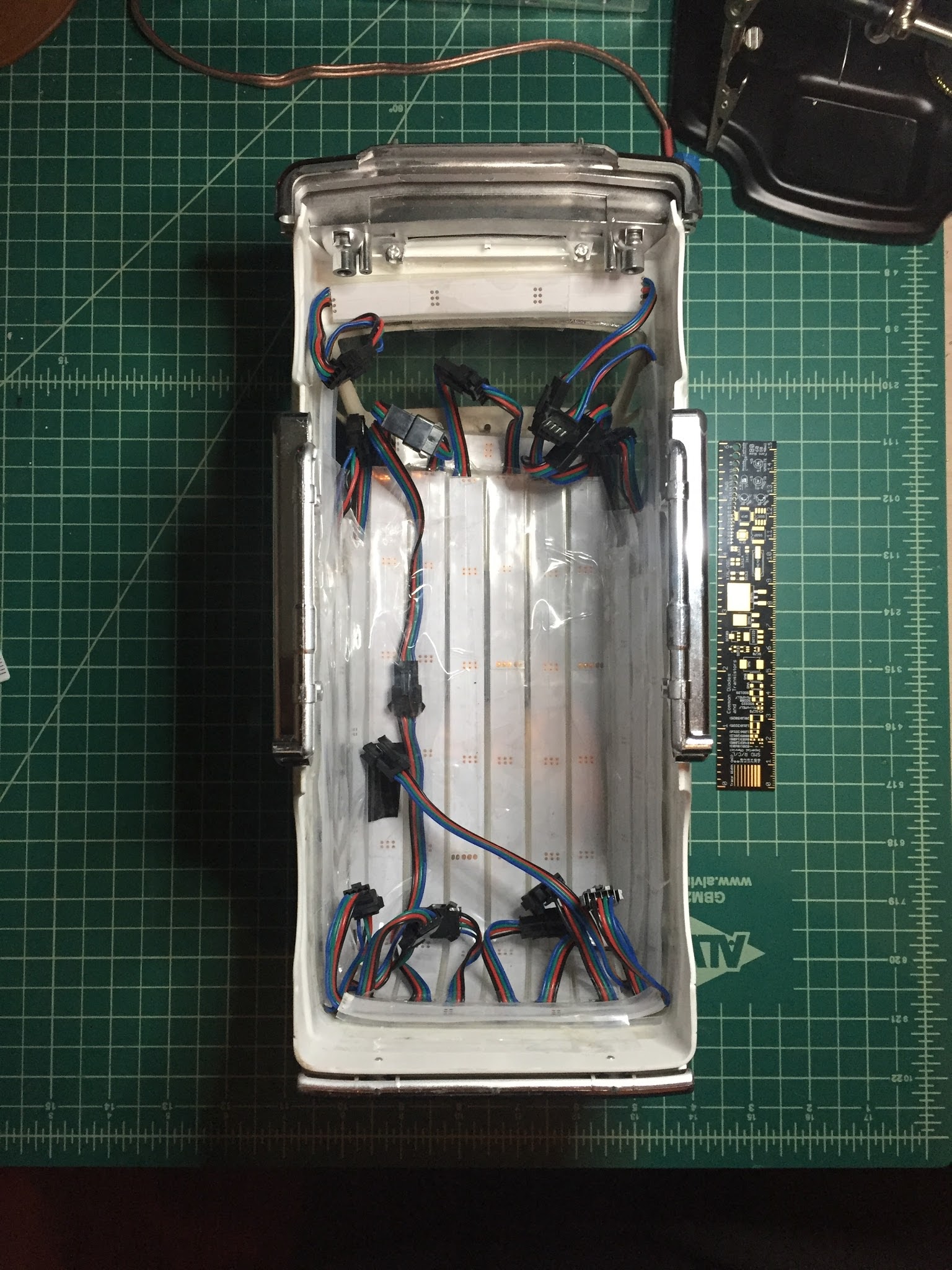
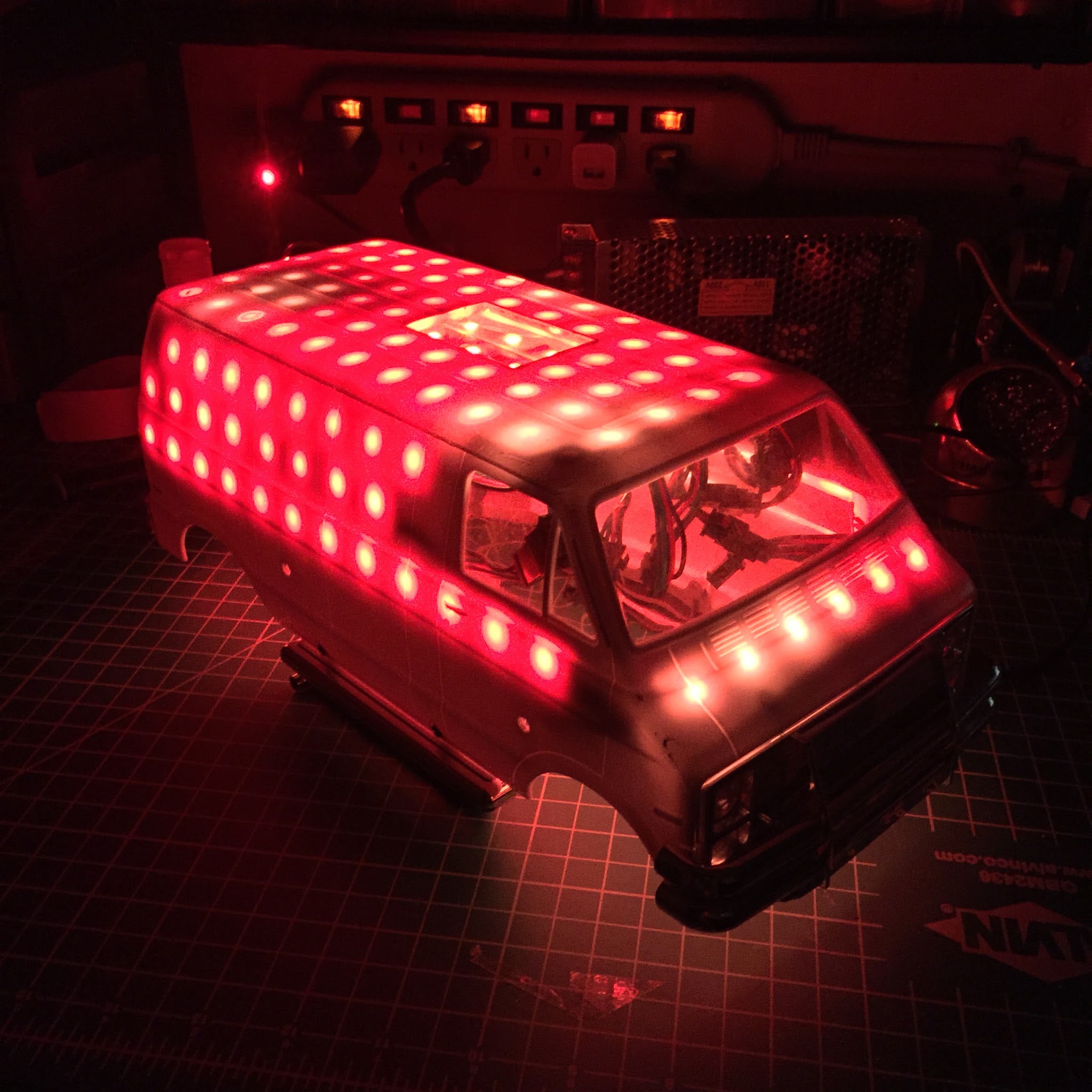
I came to this solution out of necessity. I used LEDs I had on hand, 48ppm IP67 LPD8806 from Ray Wu, and soldered 4pin connector cables to make it easy to replace a strip if anything funky happened. At first I only wired up a small ordered grid covering most of the top and a bit of the sides and rear. I soon realized I needed more LEDs as the form of the rc car wasn’t coming through with the first set of LEDs. I wired up a few more strips and placed them here and there where they were needed to fill out the shape. Now it looked nice, but the data was going all over the place, starting off like a serpentine grid and then ending up like a zigzag belt. Next I needed a lookup table.
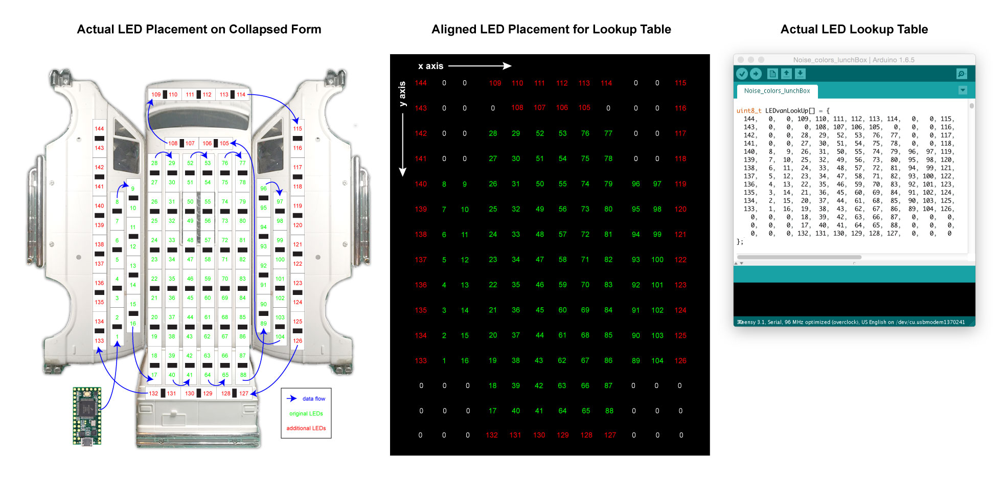
To figure out the ordering of the lookup table, I first needed to create a wiring diagram so I knew what order the LEDs were wired. For this I used Adobe Illustrator. I find illustrator to be a quick tool for me to make graphics like these. However, I could have used paper and pencil. Once I determined the data order ( you can follow the number order in the attached image, green are the original LEDs, red the additional LEDs ), I simplified the LED placement and aligned the order into a traditional grid. At this point, you might notice that I started counting the LEDs at 1 instead of 0. The reason for doing this is so that any holes in my LED “grid” can be represented with 0, and a simple if statement in my drawing code first checks to see if the lookup table value is greater than 0. I suppose I could have used -1, but I chose to use an array of uint_8s to speed things up and save on memory. This might be a good time to say that using LED lookup tables can be memory expensive, but I am using a Teensy 3.1 so that doesn’t matter as much.
Next, I created an array in Arduino and made sure to space the values evenly so the table was legible. After that I was pretty much set. I started by adjusting the example NoisePlusPalette to work with my setup. Here is a link to a pastebin with the code: http://pastebin.com/VeXPXk57
I prefer to do it where I have a an X/Y coordinate for each pixel. It means my pattern code converts an X & Y location to an hsv or rgb value, but it allows for some really complex and sparse layouts.
Keep in mind, @Matt_Richard , that @Daniel_Garcia is looking up XY space indexed by pixel, whereas it looks like your code looks up pixels indexed by XY space. Both are useful, but they are useful for different effects.
For one of my recent projects which was very sparse (with LED strips tracing contours), I did something different again: I used a graph of adjacent nodes to decide where a point of light could change “direction”, then mapped these graph nodes to pixels. The drawback of my approach was that I did not add location data to the graph nodes, so I can’t do projections into 2D space using functions like inoise8.
Very nice work. I did something similar with my Tamiya Monster Beetle many years back, using a PIC and assembler and 64 standard red LEDs. (You might have seen it on Tamiyaclub). The wiring was a nightmare, but now with addressable LEDs it’s possible to make something much more impressive and the wiring is super-tidy. I intend to update my MB some time with addressable LEDS, if I ever get around to it I will post up some info.
@Daniel_Garcia your method makes a ton of sense especially for open spaces, where my method would have an array of mostly zeros. An example could be LEDs running on state borders of a map of the US. Is there a way to optomize the noise example so it is not calculating all of the unused values?
@John_Oatham I am going to track that Beetle down. Addressable LEDs are a god send. I remember my awful rat nests when using multiple TLC5940s in breadboards.
@Matt_Richard I’ll see if I can dig out an old video or 2 and put it on YouTube - when we did the videos, YouTube didn’t exist! For now, try http://www.tamiyaclub.com/moviecomment.asp?id=1627 for a link to a WMV showing my old Beetle and PIC lights project amongst others. I came to FastLED the same route as you, via PIC chips first, then TLC5940s and then FastLED. FastLED and addressable LEDs win hands down. Now I’ve just bought a bunch of the APA102 LEDs, I think I should resurrect the Monster Beetle project using FastLED.
Just put together my first matrix and am looking around for interesting ways to program it so this caught my eye! I’ll have to take some more time to parse what you’re doing, but this caught my eye:
for (int i = 0; i < kMatrixWidth; i++) {
for (int j = 0; j < kMatrixHeight; j++) {
// ONLY EXECUTE NOISE FUNCTION INSIDE PIXELS
if ( i < kMatrixWidth ) { …
Why the if() statement? Won’t i always be less than kMatrixWidth since otherwise the for() condition won’t hold?
Thanks for the insight - Really helped with getting my Fibonacci Spiral Project going - Ceated a lookup table for each of the arms directions helped speed the mapping - Just to say If you’ve more than 255 Led’s running in your sequence then you need to modify uint8_t in the lookup to uint16_t also here to “uint16_t lookUpNum =” - Had problems trying to get all 352 Leds to map but the modifcation sorts the problem. Many thanks, and great work.