And I want to use it to drive my k40 (mostly to gain programatic laser power control)…
Can someone help me understand how to wire the laser fireing pin and PWM pins together?
The K40 has the “IN” pin, which is supposed to be a PWM pin for “power” and the “L” pin (active low?) for “activating” the laser.
the grbl has a PWM pin on the “laser” connector (with gnd and 12V).
What is the correct connection? Should I wire my PWM output to the K40 “IN” and leave the “L” alone? or should I connect the “IN” to the 5V and the grbl PWM to the “L”?
Pictures of the connectors on your Laser Power Supply (LPS)
Schematic of the controller
The approach I recommend is: Controller connection:
Connect the controller’s PWM function to the L pin. This pin needs a ground to turn on the laser. The best approach is to use a MOSFET configured as an open drain MOSFET. Usually, controllers have a driver MOSFET whose drain is uncommitted. These drivers could be designed for SPINDLE or LASER. Do not apply 12V to any interface pin on the LPS.
How well this works also depends on what firmware you are running on the controller. You may need an inversion on the PWM.
I am not sure of what connections to advise you to use.
Try and find a schematic so we can insure we provide the best advice.
Alternatively we can try and figure it out by making some measurements with a DVM.
Local Power control:
If the K40 does not have a pot or a digital panel. Connect a 10K pot from 5V to grnd and connect the wiper of the pot to the IN pin. For testing, you can just connect IN to 5V which will set the power to 100%.
This configuration will give you additive control of power from the control panel and a running program.
Details on the evolution of this approach are on my blog.
Here is a specific post on the subject:
I also placed my grbl board on the PSU for the picture (not connected yet).
The board I am using is a woodpecker clone. The schematics seems to be similar to this:
I was really hopping to not have to add extra HW as any extra part is just asking for trouble
Unfortunately, since all the pins on the board seems to be default low… and some dumb guy decided to make the K40 PSU fire on low! it is not helping…
What are your toughts on connecting the PWM output to IN and the L pin low directly or through an extra on/off switch for safety? I know that I would loose the “double PWM control” which allows for easier max power management, but I am ok with that…
If I have to go the PWM inverter route, do you have any reference/suggestion on what mosfet and resistor to use? I know electronic “theory”, but not enough in practice to make such choices…
If you have a K40, they have the 5V control going to the IN terminal of the lps. So it should be there I would think…
As @donkjr stated make sure you use the laser pwm pin for an output. The input to the lps is a ttl level signal, same as your led laser output of the board.
So it should be able to drive it directly… but it will most likely be inverted.
This is the output of my Woodpecker controller for one of the 3018 types, probably similar to yours. You want J2 pin 2 to drive H input, that is the inverted L input… if your lps has an H input.
LPS were here for commercial use long before the K40’s inception… I worked on lots of machines and the engineers claimed there was less technical issues with active low signals than active high signals.
The problem here is in your head it’s just a state on/off, which is entirely relative. Many products work with active low signals … the Arduino, is an active low design… You probably associate high is on and off being low… think of it as on/off then you don’t have to change how you think of it…
The Arduino (if that’s what’s in your controller) has the ability to invert that signal… at least the hardware does… if you want to get into the controllers grbl firmware, that could be modified… Someone may have already done so.
Actually, no, the problem is not in my head… I have done lots of HW/SW and am very familiar with inverted logic…
No, the issue that I am facing here is that most CPU (and this includes the arduino) have default/reset low values for GPIO. So if I was to wire directly one of the aduino GPIO to the K40 L input, even if I was to drive it high as soon as the CPU boots, well, boot can take time. Past clock setteling times and the like, most CPU have a boot process that can take from us to ms during which the laser could fire…
I actually have started looking at the grbl code to see how hard/easy it would be to change it…
Granted, “all you need is some simple HW to invert the signal”… but said HW has to be desinged on the PCB… in my case I can not change the PCB easely (I would have to make a new one which takes time/energy)…
Lots of design use active low (it is easier to design in CPUs and has less leakage current), but here, and my comment was “tongue in cheek”, it is indeed not helping
Anyhow, I will test the output of the spindle connector to see if indeed one of them is inverted. If it is the case, then it would solve my issue!
Thanks a lot for the pointer. Hopefully it will do what I need…
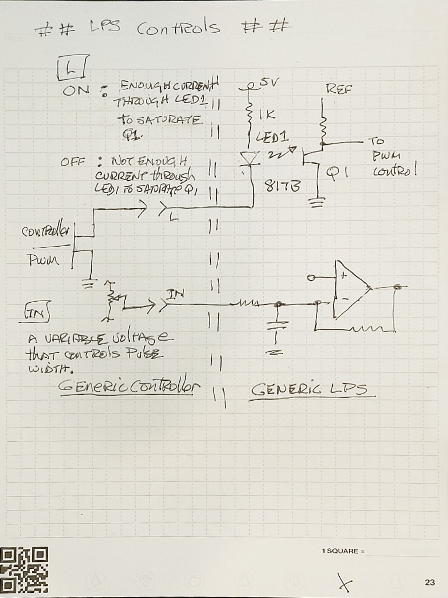
As you can see neither of these inputs is really “TTL”. That is in spite of what the manuf. specs tell us.
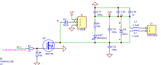
The L input expects as ground which creates current through the optocouplers LED and saturating Q1. Q1’s on-state enables the PWM in the LPS. The LPS internal PWM generator is controlled by IN.
This approach isolates the L signal from the HV supply and is not susceptible to voltage variations. This approach, also used for the P and K controls, are effective ways to interface a control switch to a hostile device.
The IN input expects a DC voltage and that value controls the pulse width of the enabled PWM controller (simplified explanation). This input is not isolated from the supply and as an analog control is susceptible to voltage variations dependent on the voltage and frequency of the signal.
Since a PWM signal is a two-state signal it can effectively control the LPS by pulling the L signal to the ground. This can be done using a MOSFET driver like Q3 in the schematic above. This produces a noise-free and isolated control of a HV power supply.
A PWM control signal has been shown to be able to control the LPS using a PWM signal on the IN port. This will work if the incoming signal provides a DC swing that is enough to switch the pulse width control between max(always on) and min (always off) pulse width. This port does not provide isolation and is suspectable to frequency and voltage values.
Your supply type does not have an H and L control only the L control.
If the GRL firmware switches Q3 to the on state when the PWM signal is in the high state, using Q3 as an open drain will work.
I vaguely recall some kind of inversion problem with GRBL but I do not know the configuration that occurred. A search of this forum could shed some light on that.
I also recall that the PWM signal direction cannot be changed in the GRBL firmware.
I hope the above info will help you decide your approach.
GRBL has lots of inverting option both in the code, if you want to build with specific defaults, and via GRBL settings which can be changed when running( $$ shows your GRBL settings ).
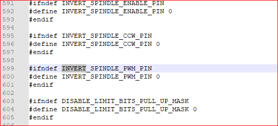
Look for “INVERT” in this file and see all the options and their defaults. The file is from GRBL-STM32. defaults.h.scad (15.5 KB)
This pin is to generate a “PWM enable” signal (direct or inverted) in addition to the PWM signal itself. To do this, it repurposes the spindle direction pin…
But, on my board, the direction pin is not wired
So, my plan is to indeed use this function BUT, to also rewire the spindle dir to one of the Z limit (which I will disable). All this in SW of course so I have no HW mods to make…
Thus I will be able to connec the PWM to the K40 IN and the spindle dir/enable to the K40 with the proper inversion (and I will most likely add an interuptor in series in order to secure the system against un expected laser fiering at startup time…
[edit]
I think that I have the SW working ok now… But I just noticed one thing, there is a 100ohm resistor after the spindle “enable” pin, which means that they will be a 100r between the ground and the L, is this ok in your opinion?
It would be useful to provide a schematic diagram of what you are doing as its become unclear to me.
In any case you do not want any resistance between ground and the L pin as this may inhibit the Opto from fully turning on. I did that exact thing once (for a different reason) and got intermittent operation.
You should read through Don’s blog on the K40 and the K40 Intro at the top of this page.
You’ll then see that the standard K40 is wired to the LPS very simply:
A POT is wired across 5V and Ground with the wiper connected the the LPS-IN input. This sets the max output of the laser.
Next, LPS-L is used to fire the laser, ie a single control line does everything you need and this is how all the Smoothieboards do it, how the M2Nano boards do it and most GRBL boards do it.
Rather surprised to see nothing else done to get the motion control stuff moved to the new controller as that can require some connector wiring at the end stops and even moreso if your endstops are other than purely mechanical endstop switches. The stepper motors should just connect up but you might have to swap wires if the directions are correct for the defaults set in your GRBL firmware loaded on the controller.
I noticed that controller is running on an AVR 328p chip which is an 8bit chip and pretty much everyone in the industry has moved to 32bit chips. It will work just that the software, grbl 1.1f is stall and won’t be updated.
I did read through his blog and I beleive that I understood…
I also understand how people did it… but as a good engineer, I like to reinvent the wheel
Joke aside, using stock parts, I was trying to get acheive a double goal:
I was trying to get rid of the extra inverter HW. I know that it is just a mosfet and a resistor, but finding/ordering/receiving them, plus the soldering, plus some loose electronic running aorund did not seem like a good idea to me. In addition, I thought that it could be done in SW, saving $ and risks associated with said loose sub-component.
The double PWM control just feels weired and I am frankly surprised that it works…
I do like the double power control that the “standard” sollution provides, and I might still use it with a potentometer on my PWM output… But I also like the simpler end result that I feel I can acheive with a more SF oriented aproach.
So, what I have done yesterday is to modify grbl so that I have a pin on my board which is an active low “enable” pin.
GRBL has this capability natively of course, BUT the board that I have did NOT expose the standard pin, so I had to change the pin configurations in a non standard way, which killed my Z switch (which I do not care because I do not have a Z axis)…
The only thing that I do not like at the moment is that it takes around 1.5s from power up to full SW init, and during this time, my enable pin is low (laser on). However, since PWM is at 0, it should not be a problem… But I am working at reducing this delay as much as possible…
grbl 1.1f is actually very good (I use it on my cnc), and yes, there is not a lot of work on it… because it works and does what you want it to… However, it is also very easy to modify if/as needed… and at less than 20$ for a fully populated board, it’s a prety good deal
I will keep this thread updated once I am complete to provide a conclusion, one way or another…
Commercial boards, like the Ruida and Trocen run the pwm to the IN input, then the laser is enabled by the L input going low, which fires that laser. The pwm on these runs continuously for each layer as it executes them. The pwm, on these, does not control if the laser is on or off.
My lps also has an H input that is an inverted L input for laser enable. Does your lps have an inverted enable input… ?
If you set your power limit within the lps, then the percentage power setting will line up with the software…
Thanks for the info.
Unfortunately, I do not have an inverted “enable”… So I have to switch it by SW (or do a HW modification). The issue is that SW switch only takes effect once that SW has started (which takes around 1.5s due to the boot loader)… Fortunately, during that time the PWM is also at 0… So I hope that this will not be an issue:
Boot = PWM=0, L=low (laser should fire at 0%, so not)
After 1s: PWM=0, L=HIGH (laser does not fire)
During use: PWM=value, L=LOW (laser does fire at appropriate %)
Good thinking, I did not think about this. I was looking at the value on the pin and was reading 0V. But in tristate mode, it would work… Safing the system.
In case someone wants to do the same thing as I did. It is working!
The steps are:
Modify GRBL to invert the spindle enable pin (INVERT_SPINDLE_ENABLE_PIN)
in my case, I remapped the spindle enable to the Z limit (SPINDLE_ENABLE_BIT) (and the Z limit to the same pin as Y limit). As my board did NOT have a wired spindle enable pin available.
added a call to spindle_init(); at the top of main to make sure that it would be driven high ASAP at boot time.
added some wires (male JST VH 3.96mm for the power and jst xh 2,54 for the signal (laser ON and PWM))
No need for HW inverter for the laser!
Thanks to the grbl comunity for your help!
Cyrille