How are people installing their saite_cutter 18mm ZnSe heads. I’m having trouble getting the mirror to sit in the laser head. The provided washers look like they are for a smaller lens. I found some files to cut a mounting bracket, but a little lost on the lens placement, think I got the mirror down. I saw someone using a rubber o-ring to secure it but wasn’t really sure. Thanks all!
Think I just figured it out, didn’t realize that laser head has a screw on the top, looks like it mounts in between gonna give it a shot
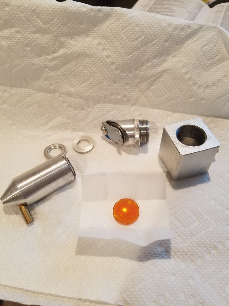
Thats how mine is i stalled,
The mirror goes in the recess under the spring clip, then the lens goes under the knurled ring in the nozzle. You’ll have to leave off the threaded ring (on the mirror mount), and put a few felt shims or a thin o-ring between the square body and the factory plate, then tighten it up by screwing down the mirror holder. (The shims provide compressibility so that you can adjust it) You may need shims on top of the plate to get the beam lined up in the center of the entry hole - the threaded ring is too thick. (adjustment required so that the beam goes out the nozzle cleanly) - it’s all a bit of an PIA, but well worth it…
Got it mostly assembled now thanks, couldn’t I just take a drill press to the orignal bracket and drill it out to 20mm?
That’s a requirement, You DO have to open the hole up. I forgot the mention that, sorry.
With the lock ring, it’s the height that is the problem. If you leave the ring on, it sets the mirror mount too high (above the beam), without it, it sets a smidge low (about .020). It’s on my list to make some ‘adjustable’ Plates for people with that head. You COULD shorten the 3 standoffs a bit and that would do it too. They all have slight dimensional differences, tolerances on the parts are pretty loooose…
I bored my hole and got everything screwed together, now the laser cutting head is way to close to the bed. I’m trying to raise it with standoffs. Can you show me a picture of the o-rings/shims I bought a bunch of o-rings just not sure exactly where to put them I get the idea but a picture is worth a thousand words.
Actually just gonna rip the clamp bed out, it’s crappy anyways. Any suggestions for cutting the air duct to increase space as well?
I used a dremmel with cutting wheel. It seems like a lot of people remove the whole thing, but most of my work runs right in front of it so I kept it, but trimmed it.
I do see advantages to removing it or making some decent modifications. As-is it only seems to draw out surface air, but sometimes you need to draft air from under the work as well.
Either way, you’re going to love the air assist. I have the same head.
Set the machine up to cut, turn the power down to 0 and put a piece of masking tape over the opening on the entry hole of the head. keep pulsing and bumping up the power until it just marks the tape.
Adjust the height as required with the shims (mine are just washers cut from green hobby felt in the laser, (scissors will work if the laser is down) about .006 or so thick compressed. I used 5 or 6 Under the plate to move the head downward. You may need something different.
The reason it’s so important to get the laser entering the hole dead center is that it will deflect at an angle and hit the air cone internally if it’s not lined up in both axis perfectly. Adjust the Left/Right" axis with the height -raising the mirror moves the vertical beam to the right. this moves the mirror. Adjust the forward/Rearward movement of the vertical (post mirror) beam by rotating the head in the plate -Clockwise moves the beam rearward.
The best way I’ve found to make these adjustments is to remove the lens and re install the air cone. Put a piece of masking tape on the nozzle (add a little pencil graphite to the nozzle rim to shoe the “circle”) and do the low level firing until you leave a mark. remove the tape and you will see whaer the beam is aimed. Fine tune with head height/rotation until you’re right in the center. Re-install the lens.
Other useful bits - you can tell if your “missing” the hole by running the laser at half power with air off at a workpiece for 15-20 seconds then shut it down and quickly feel the air nozzle . if it’s warm , the beam is hitting it internally.
One other trick is if you’re missing the nozzle hole by so much you’re not able to mark tape on the nozzle, you can completely remove the air nozzle/lens holder assembly, and put a piece of tape directly on the rectangular block. Get it in the center there, and move on to the tape on nozzle method.
Commons sense and patience will win the day.
One last trick. If you find yourself confused or results aren’t making sense, stop and draw yourself a sketch of the beam path, that usually will catch your mistake. it’s hard to mentally follow all the direction changes and reversals as the beam bounces through the mirrors. Don’t forget the lens also reverses the direction…
One more thing, your focal point will be about a cm lower than the stock head (it’s the difference in distance between the mirror and the lens in the 2 heads), but you’ll find there’s still plenty of room for workpiece depth. Most people just use shim blocks and a sheet of mesh (I find the disposable grill topper grates made of thin aluminum expanded metal (diamond pattern) work well (Walmart 2pack for about 2 bucks), or a nail board.
For a cheap and easy nail board cut a piece of 3mm plywod or 5mm luan and drive in 17ga x 1 inch brads about every square inch or so. This holds most work well, doesn’t cause ‘reflection burns’ on the back of the work, and the ply doesn’t burn much as the beam is pretty defocused an inch down from the focal point.
I keep both options handy, along with a “frame” made of 3mm (1/8") aircraft ply cut to fit tightly inside the cutting area. I then set the laser to cut a rectangle at it’s travel limits. Discard (re-use) the center, and the frame can be taped inside the rails at any height to support mesh or a sheet of work material stiff enough to span the opening. I use this set-up most when cutting thin ply or acrylic.
You are correct regarding the factory “clamp” - It’s useless.
You are 100% correct about needing air draw from BELOW the workpiece, in fact, it’s MORE important than air draw from the top. (you can eliminate ‘smoke marks’ on the top by putting down a layer of ‘painters tape’)
It’s worth the effort to totally remove the factory air duct assembly. It’s VERY restrictive and removing it actually allows the use of the factory fan as long as you don’t put a lot of outgoing duct on it.
It cab be removed by sliding out the fan, removing the 4 screws surrounding the rectangular opening, and it’s free. I’m not sure if you have to remove the internal frame to get it out, if you do, plan on re-aligning at least the 1st mirror. Assuming you can sneak it out without removing the frame, it’ll be an easy improvement. I did it during a ‘routine’ dis-assembly, so it wasn’t any added work. It opens up the air path from about 1 x 12cm to about 6 x 20cm. – It’s huge.
Laser ON…
Scott
I find these helpful:
http://www.floatingwombat.me.uk/wordpress/wp-content/uploads/2015/02/K40-Alignment-Instructions.pdf