Hi Team, I have a question.

Hi Team,

I have a question. The PSU on my K40 died a few months ago and I FINALLY gave up on getting a replacement from my eBay seller and bought one. All the connections are direct mapping except for one pair. I wanted to consult with the community before I try ANYTHING to see if this is “OK”. If not I will send it back and purchase a different one. I have included a picture that clearly defines the question. Are the P+ & G connections on the OLD PSU the same as the D+ & D- connections on the new one? Thoughts?

Im sorry I cant offer much help on that front, but I do notice that the K- and K+ connectors are reversed on the 2 boards. K- is on the left on your old PSU and on the right on the new one. Looks like the tab on the connector will let you connect it incorrectly as well. You probably have to switch the wires around in the connector before attaching that one.

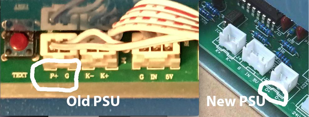
On your OLD Power Supply:

The P+ and G are your Laser enable switch (“LASER SWITCH” on the K40 panel)

K- and K+ are the “LASER TEST” switch and “G, IN, 5V” is the Power setting pot on a K40 (In takes 0-5volt signal to set power %.)

Pin #4 of the power supply connector is the “Fire” signal (5v pulse)

So…
On your NEW Power Supply:

The new supply has the 1st connectors (Laser enable and level pot), so you’re all good there,

I can’t see the power connector on the new supply, but if it matches the old one, it should be pinned as follows:
1 - 24V, 2 - Gnd, 3 - 5V, 4 - Fire signal.
Check your new supply and confirm that matches.

All else being equal, all that’s left, is the D+ and D- lines. which I’d have to bet, if I were a betting sort, that they are indeed the Laser Enable loop.

The Laser Enable loop often has more than just a enable button in the circuit, it also is the place where door interlocks, water flow switch and that sort of thing go. ALL must be closed for the Laser Fire signal to actually fire the laser.

So, connect the wires from P+ & G to D+ & D-, and she should be all good. Polarity doesn’t matter, despite the designations.

This assumes the fire command is indeed pin 4 of the new power supply’s power out connector and the 24v, Ground and 5V pins match as well. That’s critical.
1 -24v 2 - Gnd 3 - 5v 4 - Fire
Good luck!

Scott

Wow, Thanks Scott. There are a few pin switches on the power side but they are clearly marked. I will let everyone know how it goes! :slight_smile:

Mr Keneally, If you’re interested,

I’m going to try something here, if you send me your old power supply, I’ll see if it can be fixed. I suspect that most of these failed power supplies can be repaired for a fair price. If you’ll send me your supply, I’ll have alook and give you an estimate on the repairs, if you don’t want it anymore, I’ll pay postage and on it and send you 5 bucks just to get started. If this works out, I’ll be able to offer repaired supplies on an exchange basis at a much lower price than you can buy a new one for. Assuming the postage isn’t a deal breaker.

It’s worth a try.

Let me know if you’re interested ALLTEK594@aol.com

Thanks, Scott

@Scott_Marshall I am also interested in the donation of a busted supply so I can trace out the input circuitry better clarifying how to interface.

Once I have the units swapped I will consider all the suggestions as to what I do with it. Thanks everyone!!!

@donkjr it seems we have a common goal in that we both want to find out how fast we can switch the supply without killing it. I have concerns for tube life as well.
I’d be willing to bet the high voltage circuit in the supply switches at 18khz or so. That would mean at 50khz you’re trying to chop at a 1/2 cycle period or so, That can’t be a good thing.

My personal thoughts lead toward converting the PWM to a 0-5v (or 4-20ma) signal that can be used to control the laser power. That way you get all the advantages of PWM and software control, but without beating up the equipment.

I’ve designed an integrator that I hope is fast enough to do the job, but haven’t had time to prototype it yet.

I’ve seen several folks with 50-60w units that have killed the tube and or power supply by PWMing at too high a freq. I don’t understand the desire to run at such high frequencies, the head on a K40 will never be moving so fast as to need a 50khz pulse rate. Maybe I’m missing something?

Anyway, If I an able to document a supply (mine or another), I’ll post the schematic publicly and make sure you get a copy.

Scott

@Scott_Marshall Yes I am interested in identifying the dynamic and static control characteristics of the LPS + Laser tube.
To that end, I am working on a test setup that measures light output. My vacation and alignment issues have me still tinkering with the setup.
I have been skeptical of the level shifted approach to PWM control up till now because it introduces a DC bias in the PWM control that creates an error in the power output.
Even from preliminary testing I have proven that I can control the laser using the “L” input with PWM. That is what I will be using with my Smoothie upgrade and I will retain the power adjustment pot.
I also suspect that many are running the PWM at too high a frequency. I think this is because no-one knows what the systems response is.
I don’t have evidence that the LPS or tube would be damaged by to high a PWM but I do suspect that we are not getting the performance we suspect.
I also want to better understand the tubes response to short pulses at low and high currents. This will help us characterize ionization response and better understand how to use PPI types of control for high power cutting.
If you plan to create a schematic go for it… no need for us both doing it :slight_smile: I want to know what the electronics behind the control inputs to the supply are, I suspect they are optical isolators.

My blog captures much of my tinkering …

@donkjr

PSU Fans, here’s what I’ve found so far…

MY K40 supply in made by Jinan Zhenyu Electronics

This is the manufacturers page (look at ‘service’) there’s specs and such there, minimal, but some info.
http://en.jnmydy.com/products_list.html

Inputs P+ and K+ direstly drive these optos:http://www.everlight.com/file/ProductFile/EL817.pdf

Driving this PWM Controller by good old Texas Instruments
http://www.ti.com/lit/ds/symlink/tl494.pdf

Inputs are speced at 5v, but look to work on 3,3v (show 3v logic High)

It’s pretty conventional switching supply stuff from there. The Hv circuit seems to be a flyback running at about 440hz (awful low) with a tripler output.
300W 11kv nominal 4-20ma (26kv insulation breakdown)

More to come,

Scott

@Scott_Marshall awesome, did you get these electronics specs from the actual supply? When you say “driving the PWM controller by good old Texas Instruments”; is this the chip that is internal to the PS?
When you can, please let me know what the H and IN inputs are connected to.

The final HV specs are from the website, the TL494 PWM chip (SOIC 16) has the state of Texas on it, and it’s a good TI part number. Could be a copy, that’s going around, but that’s what’s in there.

The Opto Isolators, were easily traced to their source via their ID numbers

@Scott_Marshall Figure three’s notes are interesting:

From: http://en.jnmydy.com/comcontent_detail/&FrontComContent_list01-1285720952066ContId=4&comContentId=4&comp_stats=comp-FrontComContent_list01-1285720952066.html

Notes: Two options for energy control signal
A: (RF laser) pulse generator: laser intensity: 20kHz~50kHz, variable duty ratio: 5V
B: 0-5V analog signal
Figure 4 Low Level Light Extraction TTL Signal Connection Diagram

I think this suggests that in this configuration:

The IN signal is a 5V PWM signal of 20K-50kHz
or can be;
The IN signal is a 0-5V analog signal.

This is consistent with my research for PWM control however the other type supply (like I have) which has different control pins has a L pin on the DC power connector.
Where does the DC power on that supply come from and what is on that connector.

The 5Vdc is pin 3 of the power connector fed by one section of the switching supply. it’s feeding the high side of the opto isolators thru 1k pullup resistors. (thus active low)

I have 2 ordered as mine has developed a ground fault (thus the speedy dissection). It looks to be an interstage pulse transformer leaking. figures it’s one of those parts.

(I misread the 440hz in the specs. that’s max line freq - Thought they only used that in airplanes.)

Yes, on the inputs the 0-5v looks to be voltage dividered with a trimpot and probably feeds the comparator against the internal 5V regulator in the TL494 and the 2nd comparator is the feedback loop

Thanks for the info, I look forward to reading thru your research and learning about the more exotic controls. I’ve wondered what it would take to try RF drive. Can you use a standard tube?
Can’t wait till I have some time to play with this.

Thanks, Scott

Watch out for the test button on the power supplies. On mine the small momentary test button was not connected!!! The trace was not connected anywhere on the circuit board.
It was firing only from t he front panel. not from the test button.!

1 Like