Hi Guys,
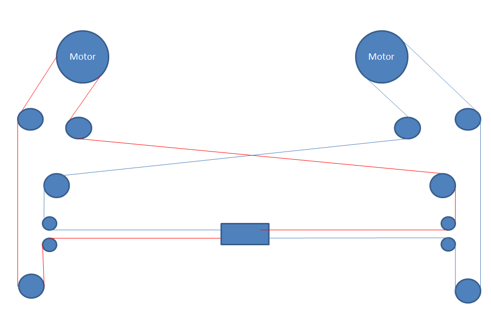
A while back I posted a gantry system that I wanted to build , the core XY system with belts crossing over at the back.
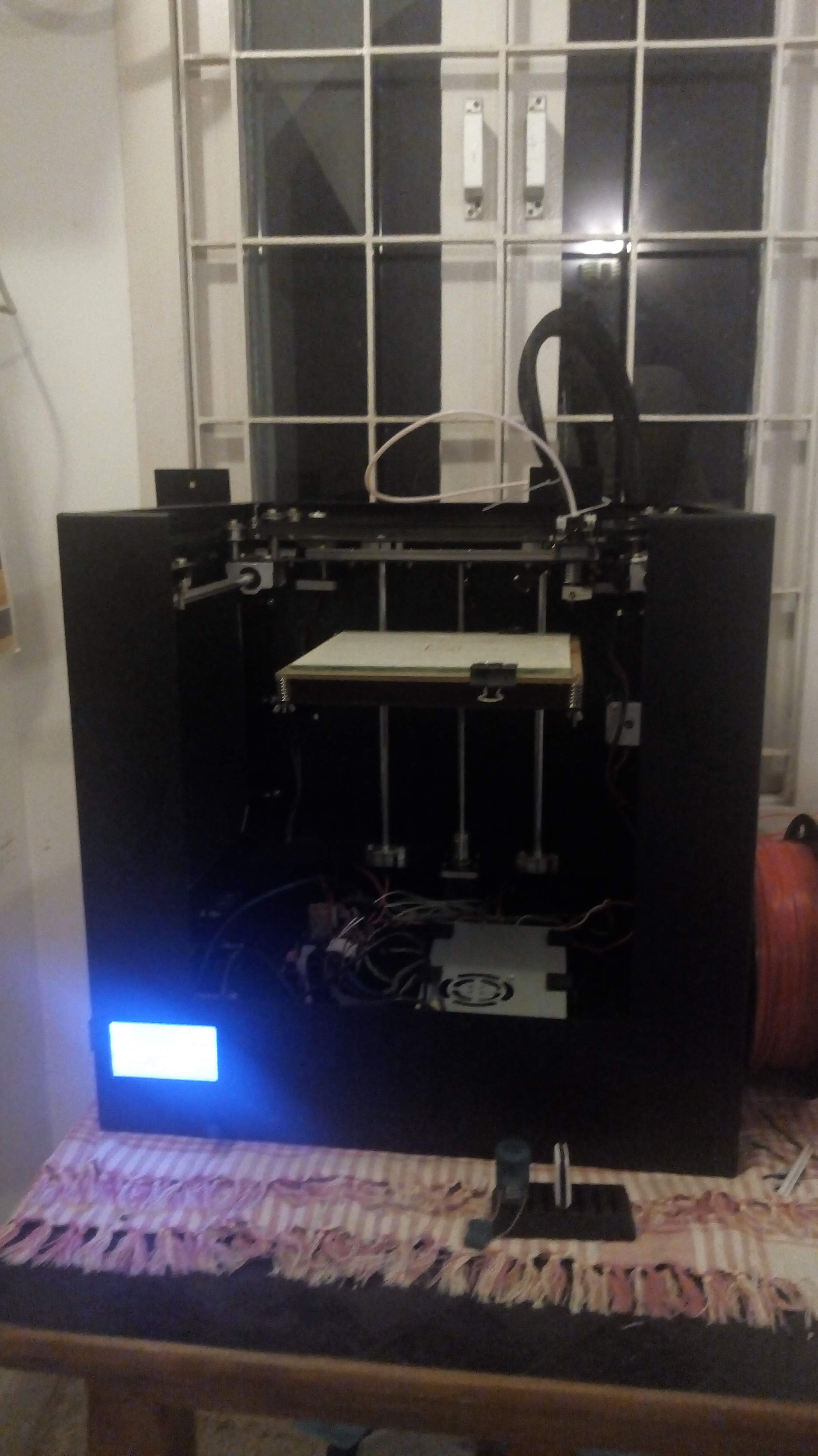
I have built the machine and the X Y gantry seem to work fine with A4988 drivers and stock acceleration settings available on marlin- 3000.
The only issue I am currently running into is that the Z Axis tends to vibrate like a spring board and the this create a waviness to the printed part. The bearings I use are LMH10UU for the smooth rods for the z axis and they do have some tolerances.
Any Idea what I can do to avod this vibrations ?
Should I make the Z- plate heavier ?
I would check for the alignment of the rods and leadscrews…as I saw in the Robo R3 3d printer, with the same design for z axis, the bent leadscrew lead to similar issues…
You could, maybe add more support to the bed.
@Nilayan_Paul Thanks for your reply,
The alignment is perfect. The vibration happens when the hotend is moving during infill. When its moving back and forth over a short distance. Am planning to increase the weight of the bed. Was wondering is thats the right solution
Then that might be the gantry resonating. Since it’s a coreXY system, try changing the print speed to some lower value so that the gantry doesn’t resonate. You can play with the values until you find the sweet spot. The bed in such a system should be perfectly stable since that does not move…
@Nilayan_Paul Any paticular reson for core XY to create such a problem
@Ryan_Carlyle Thanks a lot for your detailed answer,
I think the issue is from the first point, the cantilever of the bed is a bit too long.
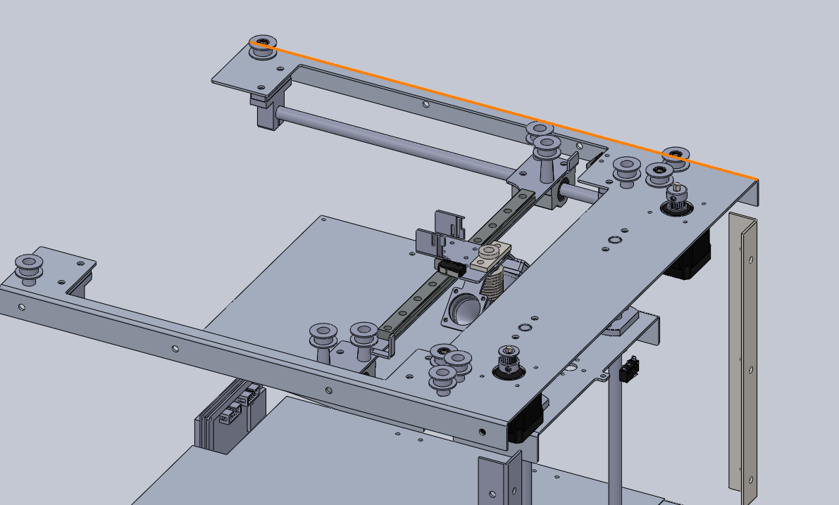
- Distance from the axis of the smooth rod to the end of the bed is 260 mm
2.The length of the z rods are are 300 mm with a diameter of 10mm
- The center of mass is 75 mm distance from the axis of the smooth rod along the Y direction and its 77 mm distance along the x direction. Not sure what you mean by bearing needs to be long.
The bed is mounted rigidly so i dont think thats an issue.
PS:
I signed up for the 3D printer engineering Book.
Do you think there is anyway of fixing the problem without designing the frames from scratch. ?
When I say bearing length or spacing - look at one Z rod, what is the total length in Z from the top of the linear bearing to the bottom of the linear bearing? If this value is small, the bearing has to resist the cantilever weight as a torque / moment load and is less stiff. If the Z bearing length value is large, the forces are side-loaded across more balls and the bearing is much stiffer.
For sliding bearings you need the Z length of the Z bearings to be >50% of the horizontal distance from the rods to the COG of the bed, or the Z stage can bind. For rolling bearings you don’t have to worry as much about binding so you can go down to 25% or so.
Easiest upgrade would probably be to go to bigger Z rods. Switching to supported rods/rails bolted to an extrusion would be better, and probably not too hard to do.
If you want to 100% eliminate the springboard, you can add two more screws, at the front corners, to get three-point bed support. Don’t know if they will fit but you can mount them on the bottom plate of the gantry would be in the way. No additional rods will be required.
@Ryan_Carlyle Thanks for your reply !!.
Am planning to start by reducing the length of the build platform and also use a thicker guage of sheet metal to move the centre of mass towards the axis of the smooth rods. The length of the bearing is 28mm , So i should try and get the Centre Of Mass at 56 mm max its currently at 78 mm
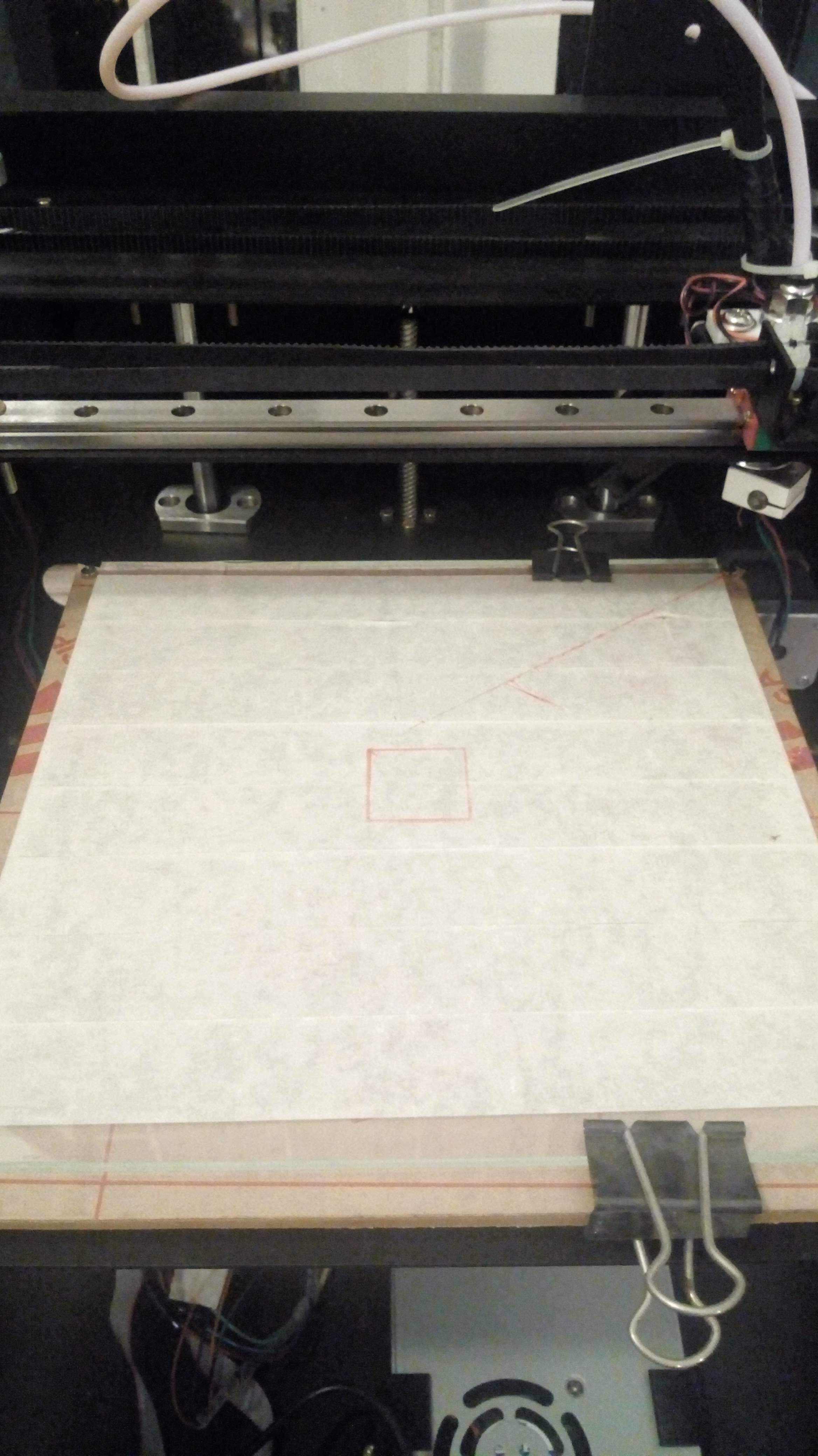
Also attached a picture of a part that I printed on the machine, It looks good from far but when you get closer the layers are not stacked up perfectly. Am not sure if its cause of the Core XY setup. I tried tensioning the belts but then i run into layer skipping issues when printing infill along 45 degress angle. Do GT2 belts have back lash ? Could that be a problem ? I also increased the voltage on the drivers to 0.9V so am thinking thats the max torque you can get out of these for now.
Thanks,
Hussain.
missing/deleted image from Google+
Another thought on the bearings, you could put two bearings on each rod.
GT2 belts are supposed to be zero-backlash. Did you buy cheap Aliexpress belts, genuine belts, or what? Sometimes the cheap belts are completely wrong — too stretchy or even wrong tooth shape.
High belt tension alone should not cause skipping. You might have the gantry out of square (binding bearings) or have a bad idler or something. To tension CoreXY belts, you should try to get them fairly tight (plucking them should make a sound) but also keep the gantry square. Uneven tension puts the gantry out of alignment. Move the X bridge to one end near the frame and check for different gaps on the ends of the bridge. Adjust tension on one belt to get it square. You may need to alternate adjusting both belts a couple times to get it square with a good amount of belt tension.
Off topic, @Ryan_Carlyle , where can I pre-order your book?
@Ryan_Carlyle Yes even I had the same question in my mind !! Would like to get my hands on one.
Here’s the notify email list signup: https://docs.google.com/forms/d/e/1FAIpQLScMr8Tg4pvVODTQiL2wzZXV6s6tMMl_q7QFEJYUB_1BHw1AxA/viewform?usp=sf_link
Publisher is wrapping up layout on volume 1 now, then we need to decide whether to do a kickstarter or what for launch, then it’ll go to press.
@Ryan_Carlyle So I got the Z axis issue sorted out and reduced the length of the cantilever below 150 mm and my center of mass is pretty close to the axis of the Z rods.
The bed does not shake at all while printing but the layers are still not tacking up perfectly. I am suspecting the belts as they are a bit loose and tightenting them causes layer skipping issues along the 45 degrees.
Pushing the gantry head manually is also extremely hard, I looked at another machine with a h bot gantry arrangement and found the belts were extremely tight but the head would move very smoothly along the x and y axis. I am missing something critical here but not getting my hand on it. Somewhere the gantry is out of sqaure or something like that.
@Hussain_Bhavnagarwal some stuff to try:
Unscrew motor pulley set screws and see if the resistance is still there
Loosen belts and see if resistance is still there
Take belts off altogether, check for resistance, and look to see if the gantry wants to be square with the belts off
Spin idlers by hand
Look for signs of stuff rubbing, black snow from belt damage, etc
@Ryan_Carlyle So I spent the last two days adjusting the belt tension, when I unscrewed the motor pulley set screw and moved the gantry head around I noticed that the pulleys moved up a bit and changed position by themselves. This made the prints a bit better. The gantry becomes easier to move on loosening the belts and harder as I tighten them.but the problem still persists. I have attached a photo of the print I did last night. It printed fine for a while so I was happy thinking I solved the problem but it was not so.
The belts are fine , infact brand new.
When the belts are off, the gantry is ultra smooth. The x axis has a Hiwin rail bearing and the Y axis has ball bearings around a smooth rod.
Idlers are also fine. I checked each one individually.
I feel the core-xy has a major problem of having both belts perfectly tensioned else it ends up in a disaster. This is probabaly the reason why most commercial machines do not offer core xy mechanisms. The H bot machine of mine works like a dream and has not needed so much work.
missing/deleted image from Google+
I’ve never had any difficulty tensioning CoreXY belts. You get both belts slightly tight to start, then move the gantry bridge against one end of the Y travel where you can look at whether the bridge is parallel to the frame. You want both sides touching whatever is the hard stop — a gap on either side means the gantry is out of square. Tighten up whichever belt makes the gap smaller. Then make sure the other belt is also tight. You might need to adjust both back and forth a couple times until the belts are tight AND the gantry is square, but it is easy and quick if you have a good belt tensioning mechanism like a slotted motor mount.
Of course, your frame does have to be square/true in order to align the gantry against the frame, but all 3D printer frames should be square 
@Ryan_Carlyle Any idea why the layer shift hapens mid print ?
guessing its the drivers heating up or something.
@Hussain_Bhavnagarwal my guess was the bearings binding from being crooked, but it could be driver overheating from too much current, or the motors skipping when they hit the print due to not enough current, or a few other things