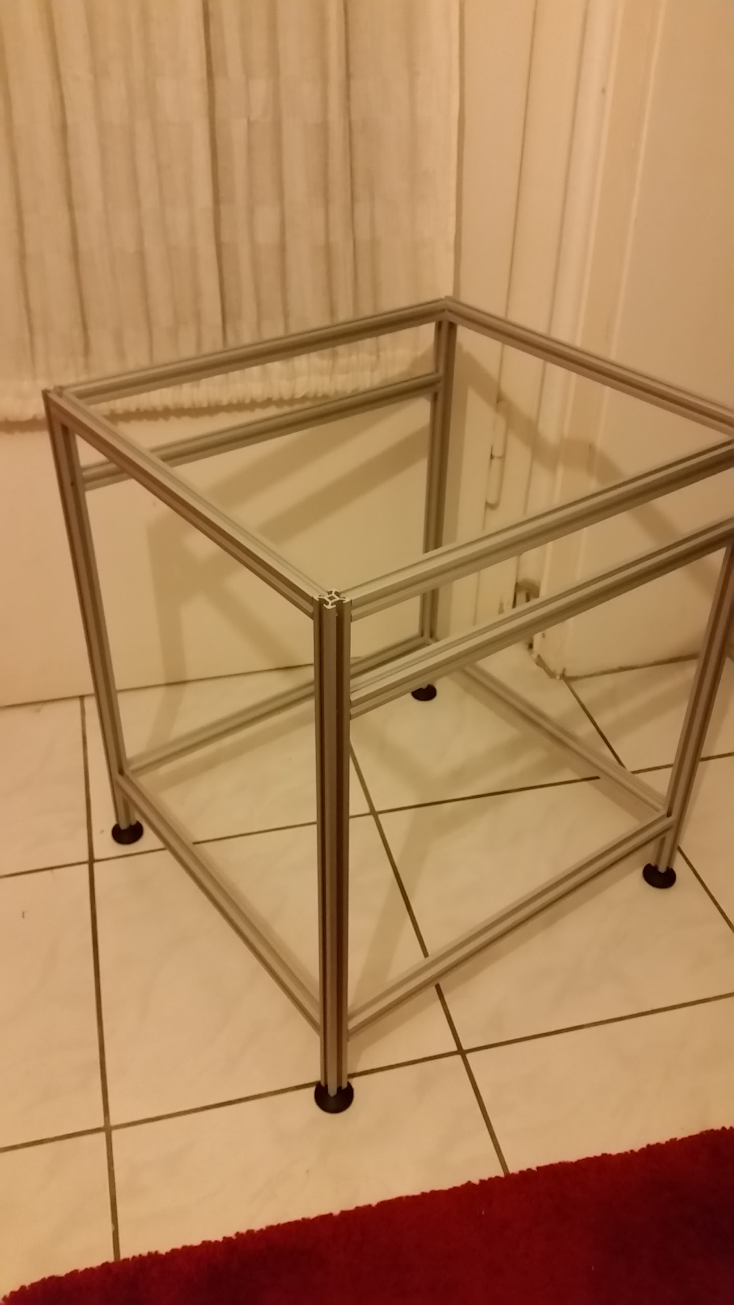
Hey Guys, i know some of you like to see the new printer beeing built so here are some pictures of my current state.
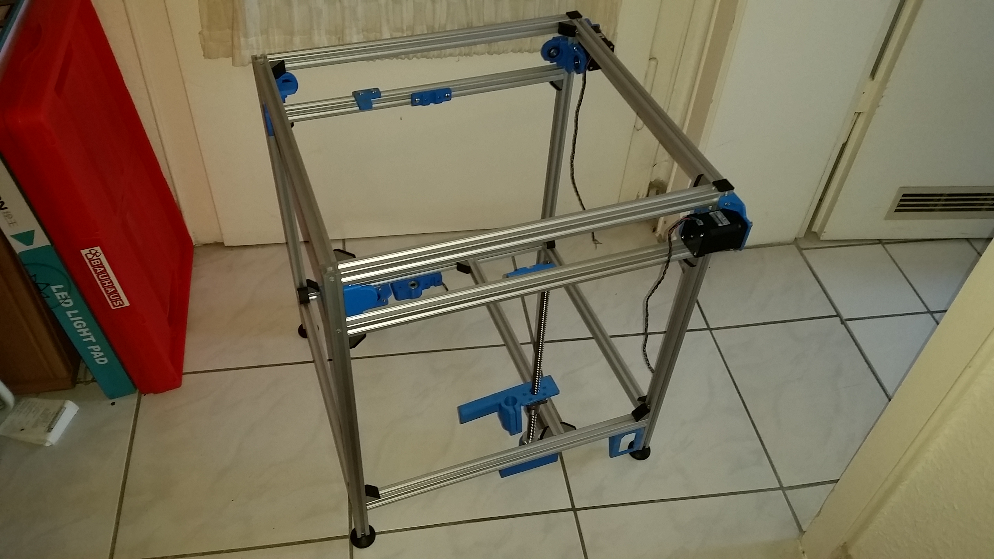
I finished the bare frame and started printing some components. I decided to extend one of the X/Y axis by 40mm so i can switch to a dual extrusion head without loosing build space if i want to.
As you can see on the second picture i am quite an idiot and only ordered one ball screw because my mind said “set = 2”. Then i printed the wrong Z-Axis bed support. I reengineered waltershiao’s bed support changes into the solidworks model so i can extend the z length to fit 2 bearings instead of the one long one (IGUS does not have long bearings).
PSU and SSR will be mounted on the right side of the additional extrusion so the area where 230V is present is minimized.
Next will be building the bed, i already have all the components but i want to try to make a pressure-sensitive bed for hassle-free autoleveling. The load cells will be mounted in the space between the bed mounting blocks and the z-axis bed support where the extruded aluminium will be cut. Because of the irreversibility of the cutting of perfectly long extrusions i want to finish the electrics and the arduino programming first so it can be tested.
@Eclsnowman : The Z_Axis_Leadscrew_Support_V2 (With Tensioner Config_hold downs and diaphragms).stl stil has only a 12mm diameter for the idler pulley hole while the solidworks file has 16mm. I could barely fit my nut holder in to tighten the nut.