Hey Guys
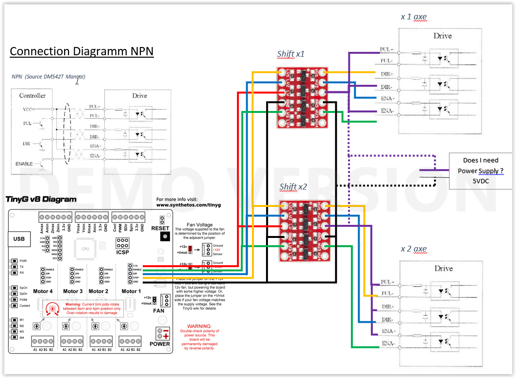
Could somebody overview my connection sketch TinyG v8 with external Driver DM542T and level shifter 3.3 > 5V.
Does I need to connect as NPN or PNP? probably PNP?
Most probably I need a 5 V Power supply. is that right?
Is there something wrong wired before I blow up something, or other suggestions for improvement?
It is difficult to comment on these as drawn because the box in the upper left called ‘controller’ , which I believe you copied from the external driver supplier, is really not correct. As an example, the Output signal “Step” (called Pulse by the External Driver) is the output of tinyG device, not the input to the base of a pseudo bipolar transistor(NPN or PNP) between that signal and the output pin on the controller.
For tinyG, the logic sense of the signals is as follows:
Enable - active low, logic 0, inactive high, logic 1
Lets focus on the Step pulse lead.
Logically, you want to connect the tinyG Step lead to the Pulse + lead of the external driver and ground the Pulse - lead.
In reality, the output impedance of the tinyG lead, combined with the input limiting resistor on the external driver results in a marginal current flow in the Pulse opto isolator input diode. The solution to this is to insert a non-inverting level translator which will convert the 3.3V logic high from tinyG into a higher level logic high voltage; could be 5V, or perhaps could be 12V.
It depends on the input specs for the Driver input and the level translator device.
Opto-isolator circuits like this typically have a wide range of voltage for logic 1, typically 5V to 20 V or more.
Why 12V? You could derive that voltage from the tinyG fan supply, eliminating the need for yet another power supply.
Same for the Dir lead; Dir(tinyG) to Dir+(driver), Dir-(driver) to gnd.
Assuming that the driver device wants enable to be logic 1, not logic 0 as output by tinyG, I would suggest to following:
TinyG Enable lead connects to a non-inverting level translator input, whose output connects to Enable-(driver). Enable+(driver) connects to 12V or 5V supply, depending on the input specs of the driver.
device. This connection inverts the tinyG logic, to be compatible with the external driver.
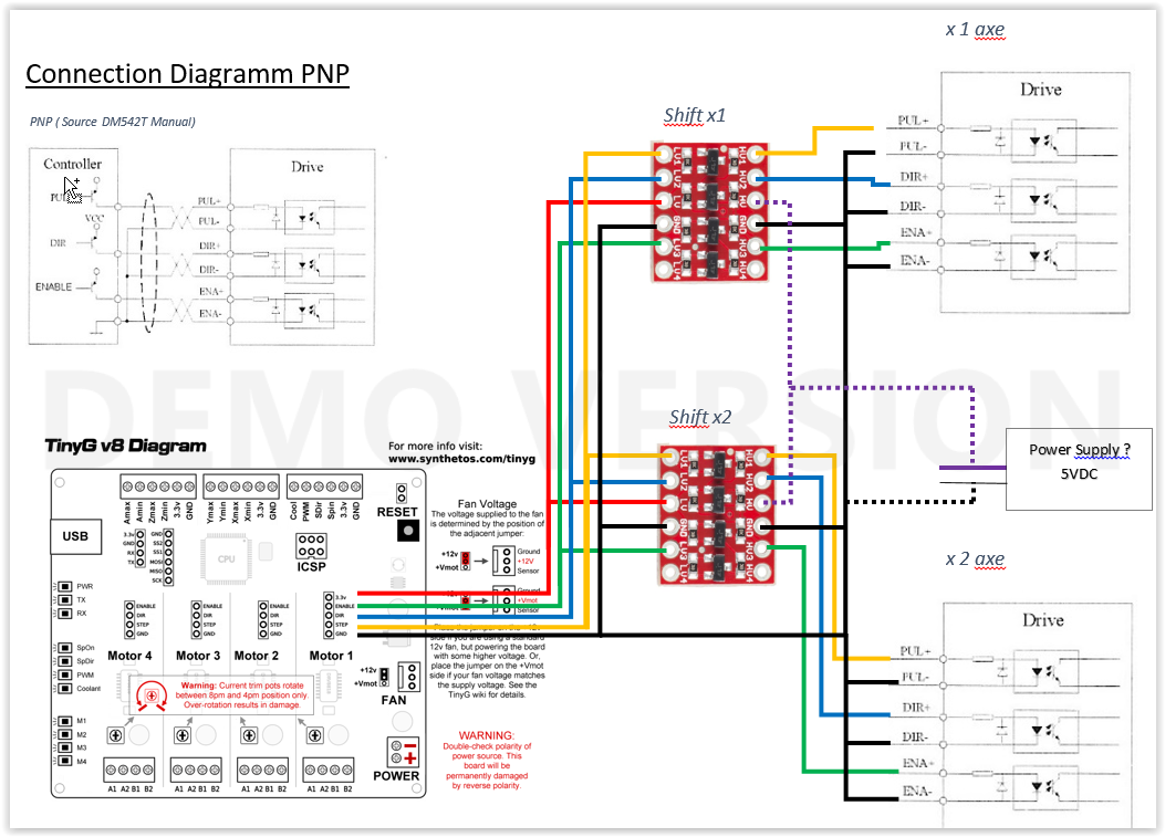
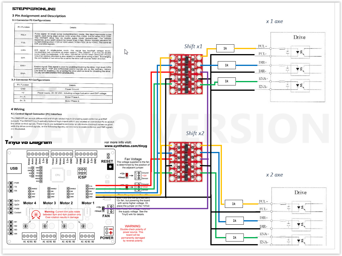
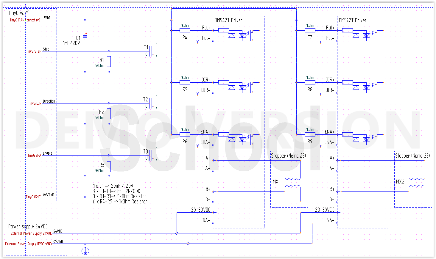
Yep I could follow your detailed explication. I changed to internal PS 12V. I also added a print screen of the Documentation and noticed they recommend an 1k Resistor to current limiting. Is the schematic now right?
There remains 1 question for the right level shifter. I couldnt find an unidirectional one on the Net. as well couldnt find 3.3 to 12V converters. Do you have any suggestion?
Your wiring diagram does not invert the logic sense of tinyG Enable, which is active low. That would be achieved by connecting ENA+ to the 12v or 5V power supply, and the ENA- lead to the level shifter output for the tinyG Enable lead.
I looked about a bit, do not find an integrated level shifter capable of 12V, so you may have to go with 5v and a 5v supply.
What is your tolerance for building the level shifter - can you deal with a raw dip package, or need a pre-assembled card such as shown on your diagram?
Do you have an old cell phone power supply in your junk box?
Cut off the connector and you would have a 5V supply, for testing purposes, anyway.
Do you have a voltmeter (VOM) handy?
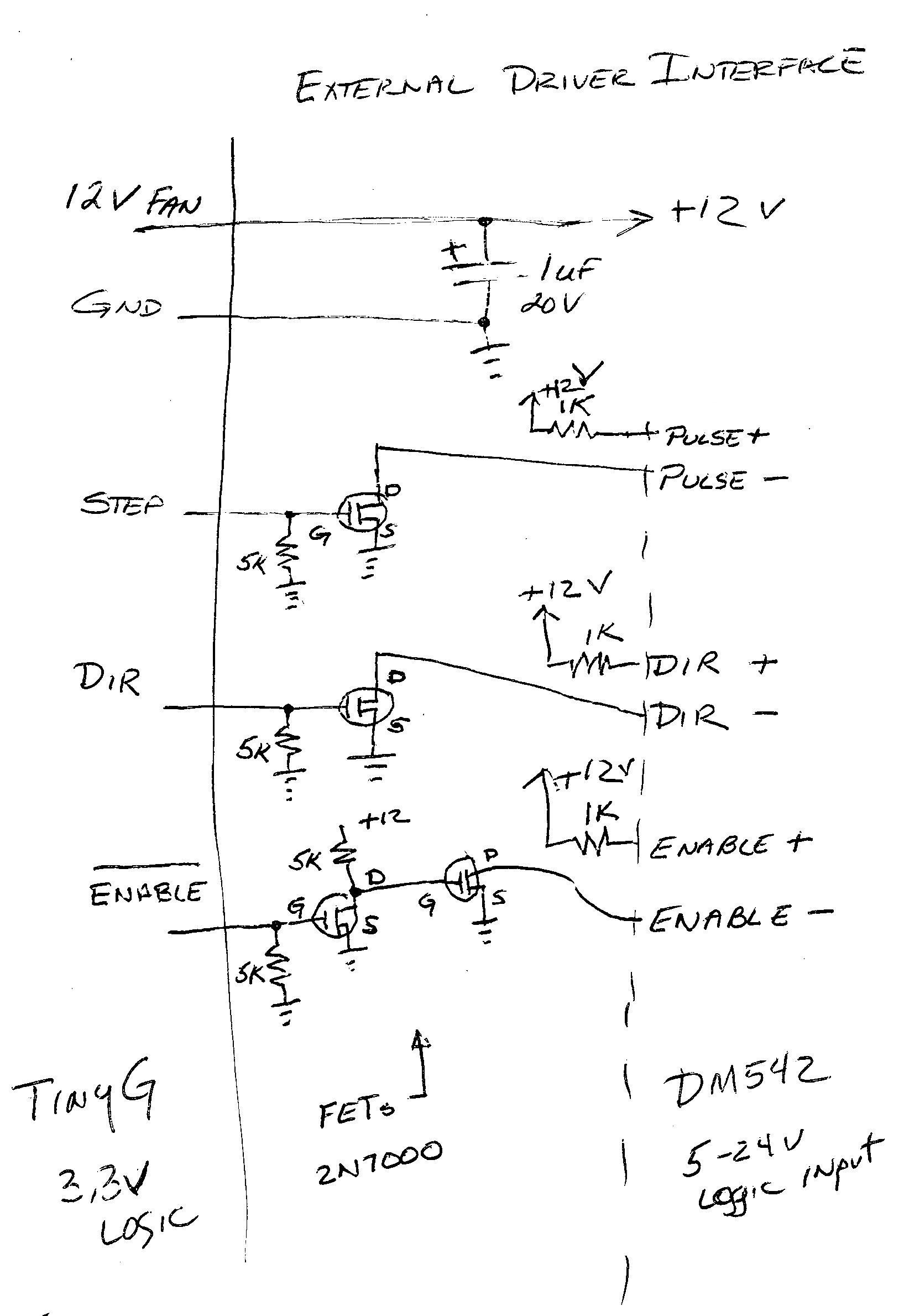
Yes I can deal witch raw dip package. If I could build one with 12V internal supply from tinyg that wold be great, but for that I need some help, to define the parts, and also on schematics. building it is minor issue for me.
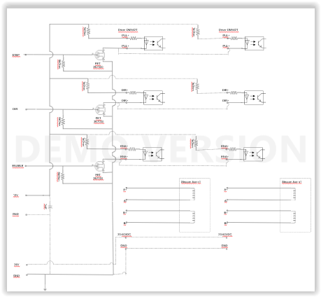
I am on holiday, don’t have a proper drawing package available so the attached schematic will have to do
The FET specified, 2N7000, is quite inexpensive (Amazon, Ebay).
Here is a spec sheet, https://www.onsemi.com/pub/Collateral/2N7000-D.PDF. There are multiple suppliers of this standard part.
Someone posted a solution using these a while back, I have used them for buffering interfaces to spindle I/O. Worked well for me, credit goes to those folks.
Logically this should do the job with the 12V supply.
Your 1K resistor suggestion will mean on current for each logic input will be around 10ma, the typical spec
I am a little unsure about possible transient (power up of tinyG) performance, added the 5K resistors to gnd to ensure the leads are not indeterminate on start-up.
Resistor values are not critical, anything close (20%) should be fine.
So I tested and Draw it for other people, connection of 2 external Driver DM542T from http://stepper-online.com and for each channel a Fet like carl sketch it up.
Speed and accuracy is just imazing the nema 23 I got connected run with 5000mm/min. with tinyg connected directly I only got 1200 to 1500 and faster Motor got staled.
Thanks a lot
I am having a difficult time viewing the diagram you drew up, but it does sound like good success. For the benefit of others, can you post a higher resolution image for folks to view?
Your results do sound as if it worked well for you,
I am a bit surprised by the extent of under performance of the native tinyG driver. Did you have the current turned up all the way on tinyG?
5000mm/min sounds a bit fast for an actually cutting (milling) speed. What sort of machine/material are you working with?
Actually the Current on X Axis I turned down to lowest, but the 5000mm/min was more like a trial to see what the 2 external Driver running in parrallel on my X can maximal handle. Also if I go to 5k speed if I would run into limit switches and mechanically could break part of machine.
Yes I`ll post a better Picture with higher Resolution, and also a toube a videao about my build. At the moment I am strugeling with limit switches, and posts are following soon.
Nice design package.
If all your motors are external, i.e. not using any of the on-board drivers, you could power tinyG from a 12V supply.
In that case you might want to switch the fan power jumper to Vmot (on tinyG) so that the fan power lead will be Vmot(=12V) rather than the output of the tinyG Vmot-to-12V regulator, which will be outputting something less than 12 V because it’s input is 12V and there is likely some minimal drop.
@cmcgrath5035
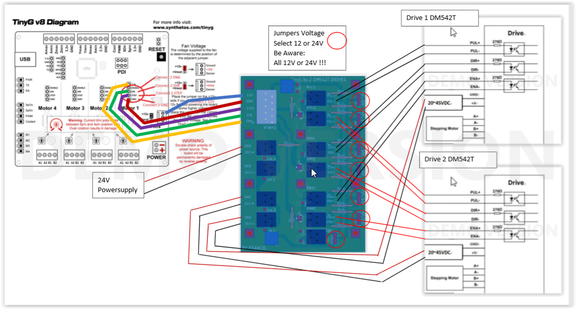
Thanks, was my first pcb design with eagle, after 20 years:)
That was basically the idee. In the overview sketch i designed it connected to 12v from tinyg. But i also wanted to make it 24v compatible, so design came up that way. I ordered 3 plates, going to test, but quit sure it will work.
Technically i made some compmise, for example used for each channel a jumper to switch the 1kohm (12v) and 2kohm(24v) for m542t drive as well for the main power supply. I didn‘t know how to make it elegant so that turn arround was ok to me.