Here's a rough idea of what I'm planning for a project;

Here’s a rough idea of what I’m planning for a project; I hope nobody minds me thinking out aloud here and if anyone has any feedback or criticisms, please pipe up.

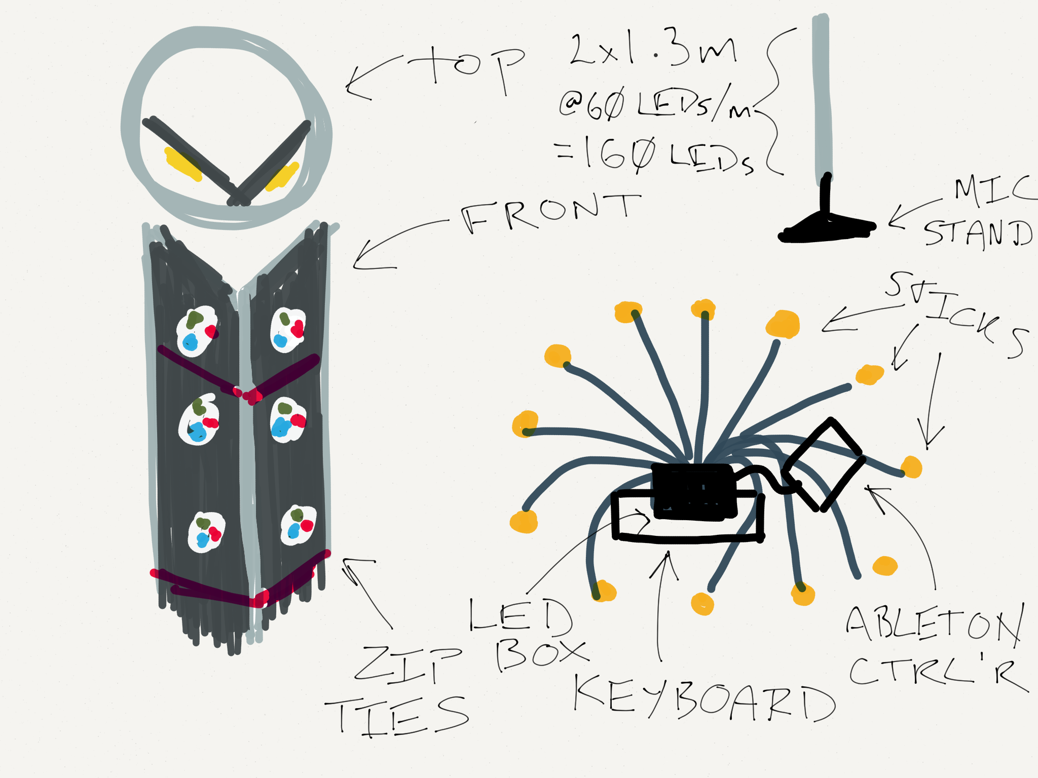
The setup consists of somewhere from 12 to 16 “sticks” mounted on mic stands, placed in a circle around the performer (whose setup is a keyboard and an Ableton controller plus a laptop.) They’ll be a bit lower around the front so you can see his face and a bit higher at the back so he’s kind of “encircled”.

Each stick is 1.3m long, consisting of a perspex tube with a piece of right-angle aluminium channel up the middle. There’s 80 LEDs worth of 60 LEDs/m strip up each outside face of the channel, stuck with the standard adhesive and zip-tied through holes drilled in the centre of the channel.

That means 160 LEDs (9.6A @ 5V) each stick. Somewhere between 576W and 768W total depending on whether we go for 12 or 16 sticks.

For simplicity, I’m thinking to put the PSUs (4 x 200W) and the controller (Teensy 3.1) in the one box, under the keyboard, with one cable going from the box to each stick.This way it can be plugged into the mains in one place and it’s easy to tie all the grounds together, plus I can run the signal for each stick from a different output pin on the Teensy and not have to worry about a signal cable snaking all the way around the circle.

Using WS2812Bs, 160*30µs = 0.0048s per frame in parallel, which is an upper bound on my frame rate of 1/0.0048s or a bit over 200fps. Which I think is plenty. I don’t plan on doing anything particularly computationally intensive pattern-wise? But MIDI (see later) might eat some CPU.

If I’m using a 3 wire chipset like the WS2812B I can use 3 conductor XLR cable to wire everything together: 8 male-to-male cables cut in half will make 16 “tails” terminating each tube; normal M-F 2m XLR cables from there to 16 x XLR sockets on the power/control box. XLR cables have the advantages of being relatively cheap, readily available, stage-proof and, if I make sure to get at least 16 gauge or better, rated for the 10A I want to put through them without dropping too much voltage.

The ultimate plan is to have patterns triggered via MIDI over USB from Ableton (I see there’s a MIDI library for the Teensy), but I’d be happy enough to have manual pattern selection and sound reactivity via line-in for a beta.

Can anyone see anything grossly wrong with this plan? Am I out an order of magnitude with any of the calculations? Am I planning on doing something that will obviously cause me to burn a stage down?

Nice project :slight_smile: I don’t know if the midi uses interrupts. I think you could even set the Serial input to the midi baudrate (so you have a buffer I think). You could also use OSC or ArtNet (with ethernet) however that might be more processor intensive. I think you would like to run the patterns and effects on the Teensy itself or not?

A cool program by the way is Vezer ( http://vezerapp.hu ).

Was this drawn using paper by 53?

Indeed @Kasper_Kamperman ;-). Not sure about the details of the Midi stuff, haven’t really dug into the library yet; Midi is all about low latency though so I’m not sure I’d want buffered serial. We’ll see. The rough plan is to have a bunch of canned effects run in realtime on the Teensy and trigger and/or provide parameters (brightness/hue/palette) to them via Midi.

And yes, done with Paper and a Cosmonaut stylus :slight_smile:

Seems like you have a pretty solid plan. Should be awesome!

One thing I would note is that XLR cables are designed to have pin 1 contact first when plugging in (or be the last to break contact when unplugging). And since it’s a good idea to have ground connected first/last when plugging/unplugging your LED strips if the power supply is on, so you might want your 5v negative wire on this pin and use pin 3 for the Data line.

However… some other thoughts… I’m not sure what problem this wiring might bring if a mic is accidentally plugged into your control box XLR jacks. Would it potentially cause a neg voltage on your data line? Would this be a problem? And… If one of your “sticks” was accidentally plugged into a mic cable connected to a mixer I don’t think there would be any problem… unless phantom power was turned on at the mixer in which case your LED strip might fry from getting 12 or 48 volts.
Would it be safer to keep your Data line on XLR pin 1 and just make sure the control box is powered off when plugging/unplugging “sticks”?

Well the buffer is just for the time your loop takes and that probably will be really fast with FastLED. If you don’t send too much data the delay is as big as the time of the loop. Midi messages are pretty short (3 bytes) and you only use it for control data.

I would suggest you use a second processor to process the MIDI and pass the requirement to your Teensy via some method.

You could send via a binary pattern on some pins, a serial character, a line change etc. Then the two can run pretty much asynchronously. The cost is a cheep price to pay for your sanity and trying to get two interrupt driven systems working within one processor.

Although the Teensy is pretty quick and could process the serial data from the MIDI to just buffer it. At some point you will have to stop updating the LEDs and do something with all the serial data. The problem is squeezing this in carefully amongst the LED output routines so neither suffers. Using a second device to process the MIDI makes it self contained and the two can ‘free wheel’ without having to be truly in-sync.

A second device can be a good idea. However midi data pretty short by itself (3 bytes) . By taking a 2nd Arduino you need to process midi data and send it out again in your own protocol… which is received by Serial. So it think you won’t win too much with it (and you need to maintain two scripts).

But well this is all fiddling around, if the direct option doesn’t work good a 2nd one is indeed a good option.

Marc; yes, I was thinking to put ground/0V on the “traditional” mic ground pin and indeed if some joker plugged one of the sticks into a mixing desk with phantom power switched on then they deserve what they get. Aside from using obscure (read: expensive) industrial control connectors I’m not sure how else to mitigate this though. I guess I’ll write a stern warning above the sockets :-).

The other type of cable/connector (suggested by the good folks on Electronics Stackexchange http://electronics.stackexchange.com/questions/150028/does-a-4-pin-xlr-cable-actually-contain-4-separate-conductors-alternatives) were Neutrik Speakon connectors, which come in a 4-pin version. The advantage to these over XLR is they have screw terminals and accept very large gauge wire so I can easily make my own to the spec I need. Not too expensive either.

As for a second processor @Adam_Sharp I’ll keep that as an option if and when doing it all on the one Teensy becomes a problem. I can’t quite tell if the Teensy Midi library (https://www.pjrc.com/teensy/td_midi.html) does indeed use interrupts and if so, if these will interfere with FastLED. @Paul_Stoffregen ?

I can’t wait to see the next iteration of your creation. I’ll have a Persian five of my sticks on the client 2015. I hope I’ll see you again. Definitely have to come to my Camp and hang out!!!

Those Neutrik jacks look really good. I guess if you got 4 pole ones but only used 3 wire (5v pos, neg, and data) that could work pretty well, and also would be less likely to have things plugged into a mixer causing potential “stick” frying.

I did like the simplicity of your original idea of chopping 8 XLR cables up for tails coming out of the “sticks” and using readily available standard XLR cables for connecting “sticks” to Control box jacks. I was wondering, maybe instead, cut up 8 female to female XLR cables for your “stick” tails and put male panel jacks on your Control box (reverse of a mixer)? This could solve the potential problem of plugging a "stick’ into a mixer, however… it does leave the possibility of plugging a cable from a mixer directly into your Control box jacks. Perhaps not any less idiot proof. If it can be plugged in, it will be, haha. :stuck_out_tongue:

I was going with the general principle that the “live” end should be sockets (http://electronics.stackexchange.com/questions/6248/sockets-or-pins-and-why).

Ah yes, totally right. Power should be in a socket.

So which one do you think is the socket then? As both halves are both male and female, so you can’t simply identify which is which. The panel mounting are accepted as the ‘socket’ only because it is panel mounting.

For this use of yours, it does not really matter which way around the speakon connectors are used:

  1. All the pins are shielded so there is little risk of touching the live contacts or the contacts shorting out.
  2. The voltages you are using are <50v AC/DC and are pretty much touch safe any how.

So just use how you want. I suggest you use plug-plug leads as most audio systems do.

You could use the spare pin to indicate that the channel is active and connected. And use this for diagnostics or to adjust the patterns.

For the SpeakON connectors yes, you’re right, it matters much less. But we found out last night that “female” cable-end connectors don’t seem to exist! There are only panel-mount ones, which is a problem as there’s no panel to mount them to on the “stick”. So, if I can work out how to buy XLR cables with a specific wire gauge it looks like we’re back to XLR.

We also decided that 2m wasn’t enough distance between the PSU/control box and the sticks, so we’re going to run 12VDC over the cables and put one of those Murata 12V-5V DC-DC converters in each stick. This allows for longer runs of cheaper, lower gauge cable (and probably cleaner power to the LEDs.)