HERE IS THE POST WE HAVE ALL BEEN WAITING FOR! ...or at least I

HERE IS THE POST WE HAVE ALL BEEN WAITING FOR!
…or at least I have.

DRUM ROLL …

The open drain, NO level shifter, No pot connections, no strange grounds, no weird 5V connections, … literally only 2 wires…

PWM control >>>>>>>

WORKS!

Just like I expected it to … I wasn’t going crazy after all !!!

@raykholo … the “Test” switch works fine along with it!

…and it works for both @Robert_Rossi and I … heh!
… and @Robert_Rossi and I have different LPS versions … heh!

------------------------
The first scope picture:
Channel 1 shows the internal PWM P2.4
Channel 2 shows the “L” pin on the LPS

The second & 3rd scope pictures:
Channel 1 shows the internal PWM from P2.4.
Channel 2 shows the lasers response to that PWM …

Its your CHALLENGE to guess how I measured the laser output … :slight_smile:

Channel 2 on the 2cnd and 3rd pictures is not what I expected and requires a a lot of scrutiny … so my list of things to explore just became huge …

Gosh I am pleased with these results :slight_smile:

fca5cb1eb8fcc144fa2b10f7d3c66c29.gif

Very Nice

As someone who knows nothing about reading scopes, why is channel 2 not what you expected?

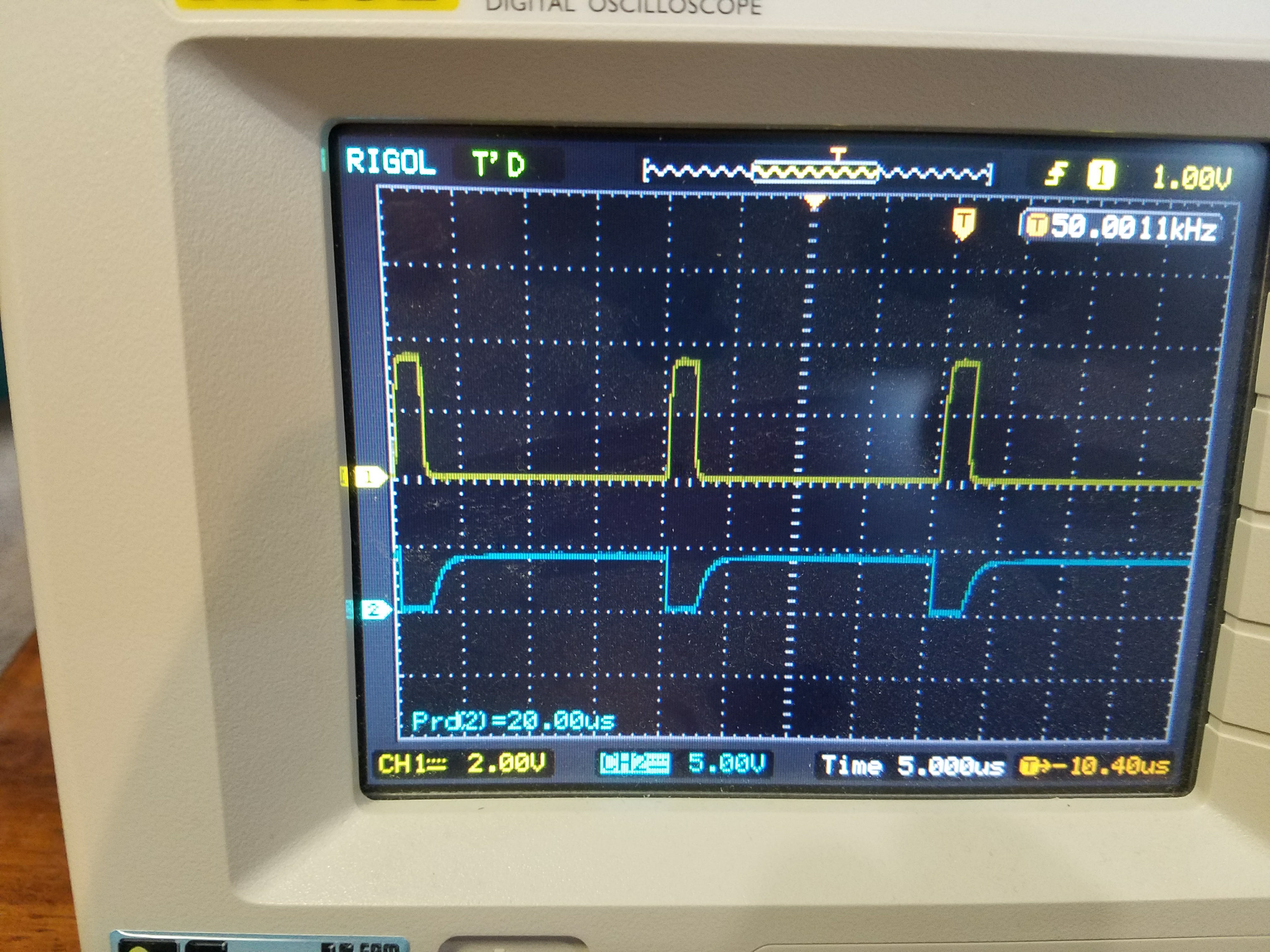
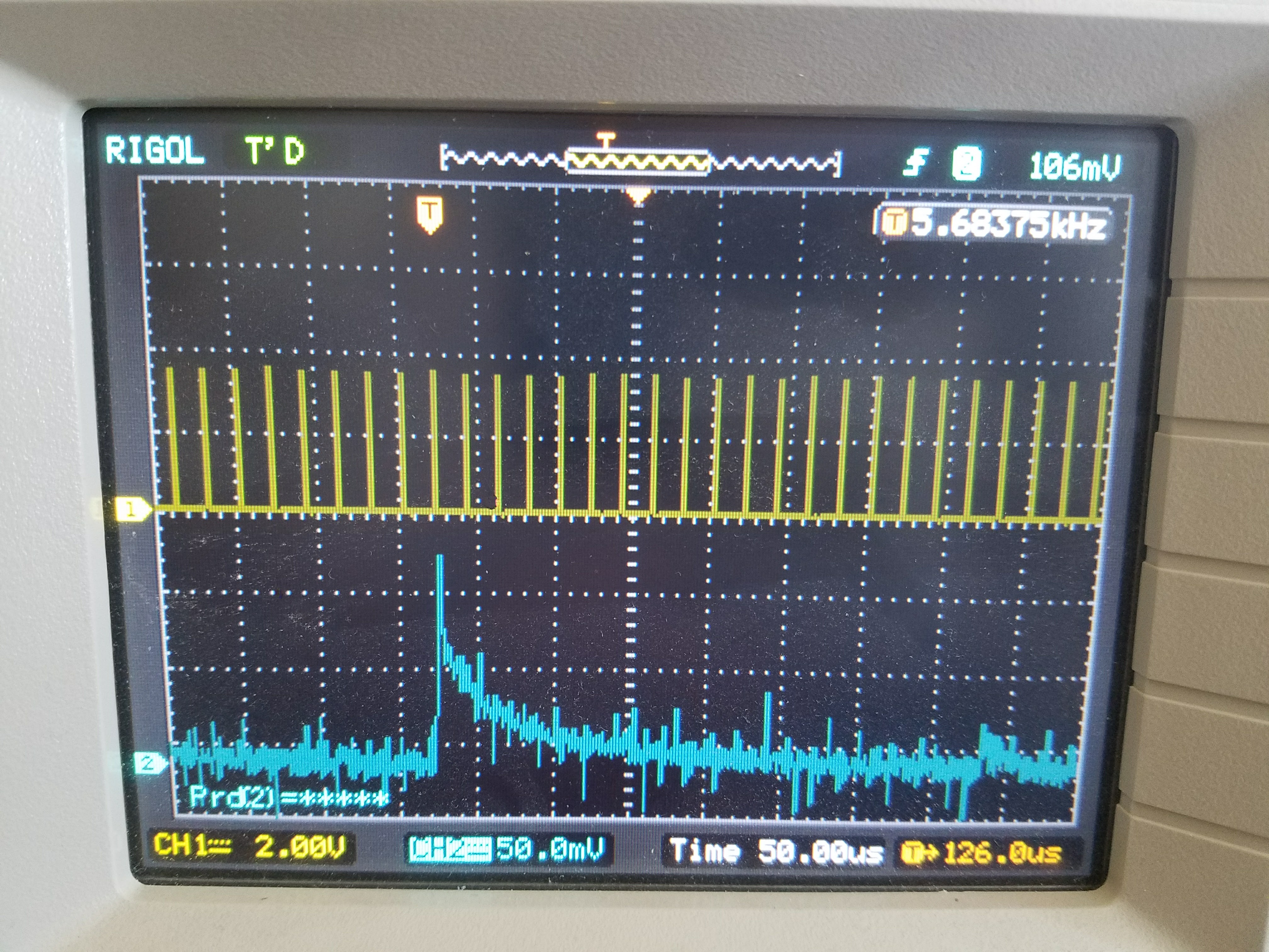
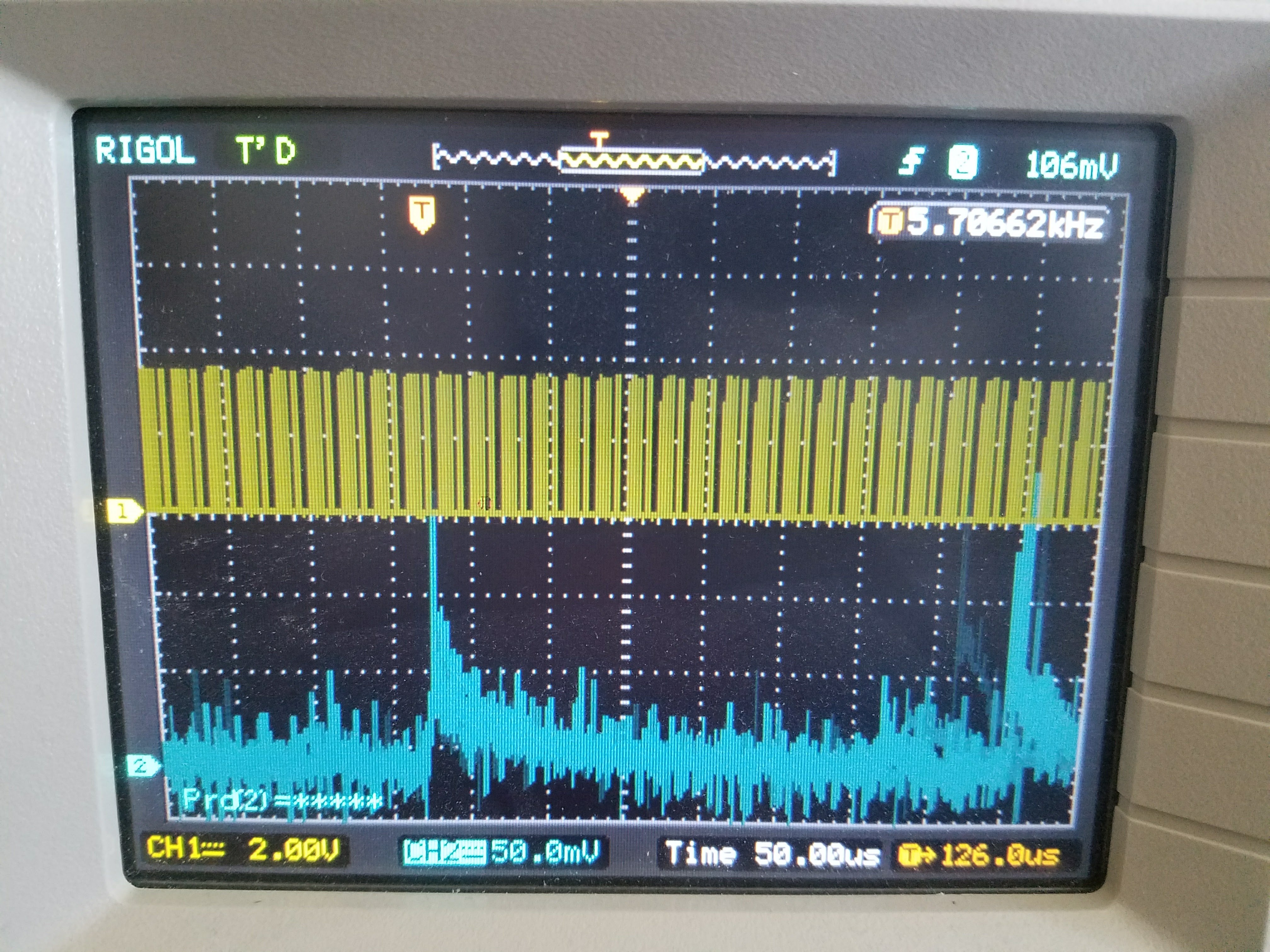
I generally expected the laser to somewhat follow the supply turning on/off at the pwm rate.
I also notice very large pulse at a much lower freq than the pwm.
I figured I would see a large excursion on leading edge of every pwm pulse as the tube ionizes.
Got to think about this more and experiment with various pwm DF and frequencies. My setup could also be lieing to me…

@donkjr Are you getting full 100% of your laser tube power? I’m assuming that’s what the open drain pin does?

@K1111 I don’t know, does anyone? Unless you have a power meter at the output how do you know? I am fairly certain that the PWM is allowing 100% though?

@donkjr I guess what I meant is, the open drain eliminates the need for the shifter, and the shifter was needed to actually pull 5V?

If you pull P2.4 raw from the processor on the main board that’s a 3.3v signal and not open drain. So you need a level shifter to get a 5v transition. However level shifter are not set up as drivers, even if they provide 0-5v doesn’t mean the are compatible with the LPS input. I don’t plan to test this config and all of this is avoided by using one of the FET drivers and two wires.
Also a post on my blog that summarizes the how and why coming soon.

What controller board?

@donkjr ​ so the 2 cables still go as you sketched a couple of days before?

@greg_greene I’m using a smoothie 5x. Shouldn’t matter though.

@Ariel_Yahni_UniKpty yes exactly like the pictorial. @Robert_Rossi ​ did also.

Hmmm, are you saying the stock board can do this???

@greg_greene the stock board M2nano works this way? This is for conversions?

@greg_greene ​ this all started as the stock board is only connected to the psu via 4 wires. 24v,GND,5v,L

Ah - so for Smoothies then "

@Ariel_Yahni_UniKpty ​ yes, that is one reason I was so convinced this would work, L is the only control from a nano to the LPS.
BTW:
I do not recommend using the LPS 5v for two reasons:

  1. It is implemented with a 7805 and provides 1amp max.
  2. I don’t like connecting the controller without isolation to a HV supply.
    Note:
    In some supplies IN is also not isolated.

@donkjr ​ how about powering the board from the 24v and gnd from the psu

I have an Arduino Nano doing this no problem at all. Why did you expect this to not work? confused
Or are you working on your own PSU?

Actually I believe many people are just using direct connections with 5V I/O directly wired to the K40 PSU.