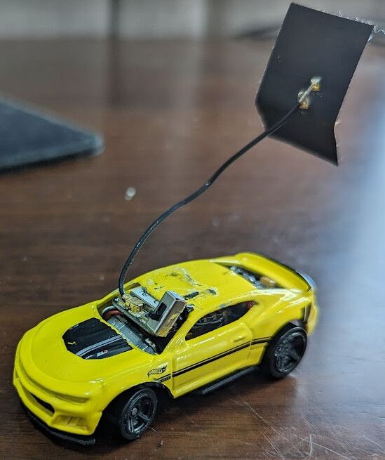
I converted a hotwheels car into an RC car using a DRV8833 H-bridge, a small DC motor, a 1.5g linear servo, and a XIAO ESP32c3, with a 3d printed steering linkage. It’s been a really fun project, but one part I’m still stuck on is the antenna.
The XIAO is nice and tiny, but it has a big external antenna. I haven’t found a good way to fit this antenna on the tiny car, so I’d like to replace it with something smaller. But searching for 2.4 Ghz U.FL antennas turns up a lot of even bigger options. I don’t need all that much range, but definitely more than I can get without an antenna.
I don’t know a lot about RF and antennas, but I think I understand that all I really need is a bare wire cut to the length of speed_of_light/frequency, so 300000/2400, or half or a quarter of that. So that’d be 125mm, 62.5mm, or 31.25mm.
Where I haven’t connected the dots yet is that the U.FL connector on the XIAO is coaxial, so there are two conductors. Which of these conductors should I connect to a bare wire of the correct length? What, if anything, should I connect to the other conductor?
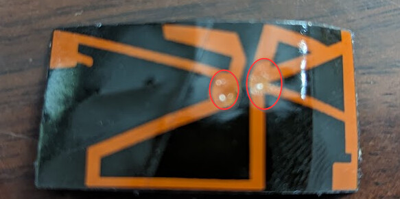
When I look at the antenna that comes with the XIAO, it kinda looks like both conductors connect to the antenna, at the points circled:
So it makes a ~54mm loop between the two connections, and then a few funky branches from each connection. Maybe the length of all of the branches and the loops add up to 125mm? In that case, do I just connect both conductors to my bare wire antenna? Or am I barking up the wrong tree?
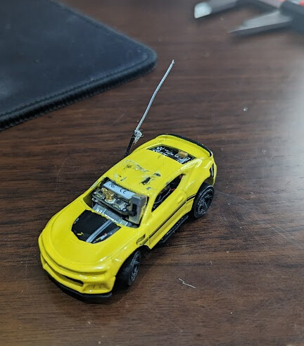
I experimented by cutting the flat sticker part off of the antenna, and then stripping the coaxial cable so that 31.5mm of the center conductor is exposed. That seems to give me sufficient range, so that’ll work for my purposes.
Here’s it is with the reduced antenna:
If anyone has suggestions, I’d still love to understand better! I’ve been reading up a bit more on monopole and dipole antennas, and I think I’m starting to wrap my head around it a little… If I understand correctly, what I should have done is saved the outer sheilding wire when I stripped off the outer insulation, and then arranged the inner conductor and the outer wire so that they were pointing opposite directions to make a dipole antenna.
The is an option, if you know someone with fritzing and a little 3018, you could make your own antenna simply by machining a little pcb. So you can kind of hide the antenna…
On one of my planes, I have the audio and video antennas as part of the skin and painted over…the are not really efficient, but they work far enough for it to be one of my planes I hope to enter in to competitions when it id finished.