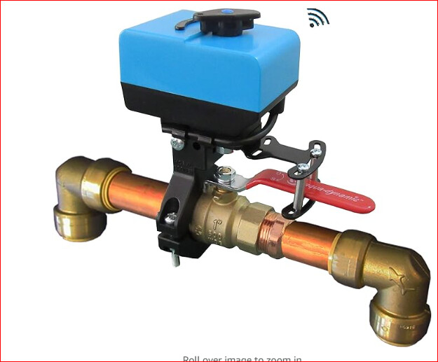
When I wasn’t able to find a controller for my valve-based radiator, built my own (link). I also figure others might want something like this, so all the plans are open-source.
The trouble is, the current design is very janky. For example, just look at how it wobbles when it rotates in the video on my website. I’d like to make this less janky, but I’m not sure where to start. A couple of things I’d like to see would be:
Adjustable grip, so that I can adapt to a different size when I move and also ideally sell this as a kit to my neighbors
Address the wobbling, perhaps by using 3D-printing (though I’m not sure PLA could handle the torque from solidly turning the radiator valve).
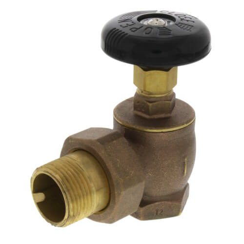
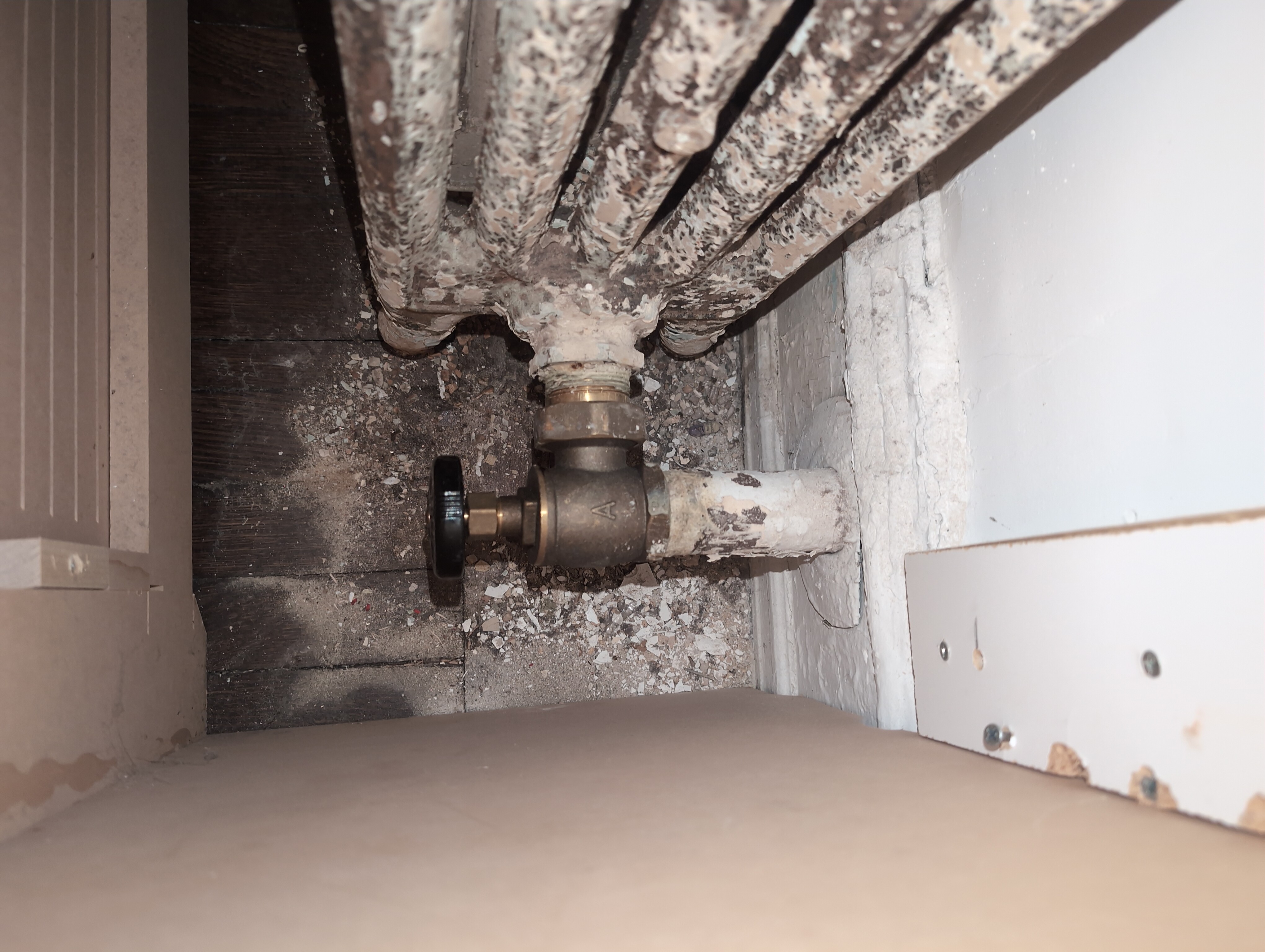
I assume you are trying to turn a valve handle based on the temperature of the room.
Showing us a picture of what you are trying to control will help us provide advice.
My 2 cents without seeing the valve assy:
The motor assy needs a better way of mounting relative to the valve and its handle. Perhaps a bracket that mounts on the pipe below the valve. The bracket would protrude above the valve handle and the motor would be mounted to this bracket. These brackets would be designed to leave on the pipe and accommodate a motor electronics assy that can be installed or removed. Alternatively, invest in one controller per shut-off valve.
For turning the handle I imagine a circle mounted to the motor with two studs sticking from it matched to openings in the valve handle. The motor/disk assy is mounted to the fixed bracket using wingnuts. The bracket stays in place the motor is removable.
Research “whole home valves” to get some ideas on how control mechanisms are mounted to a pipe.
Also, look for ways that plumbers mount things to pipes for ideas and brackets you can modify.
Wood especially plywood with screws into the endgrain will not hold or last. It is also difficult to get a motor mounted on-center using wood. Wood is not an ideal material to use near heat.
I would use metal for this project.
I would imagine you need feedback about the valve position so you know when to stop the motor. These are classical ways to sense rotation.
For turning the handle I imagine a circle mounted to the motor with two studs sticking from it matched to openings in the valve handle.
My bad for not providing more detail here. Though I suppose it may be possible to screw the motor flange directly into the valve handle. Thoughts on that?
Wood especially plywood with screws into the endgrain will not hold or last. It is also difficult to get a motor mounted on-center using wood. Wood is not an ideal material to use near heat.
I would use metal for this project.
That makes sense-- a key motivation for posting here is that I’d like something that will hold up long-term. How would you get the parts? Metal 3D printing? Any thoughts on if something more accessible like nylon 3D printing might work alright?
I would imagine you need feedback about the valve position so you know when to stop the motor.
Yep! I already have a half-working solution for this: Current sense resistors detect when the valve is shut. I allow for 10 seconds of counterclockwise motion to open the valve and 11 seconds of clockwise motion to close it. The h-bridge motor control chip includes a current-based shut off, which I’ve attached to some resistors on the board so that it shuts off after applying the appropriate amount of force. See any issues here?
Perhaps something like a premade vice-grip mechanism could hold onto the handle, but then there’s still the question of where and how to anchor the motor body and PCB so they stay still and only the handle rotates.
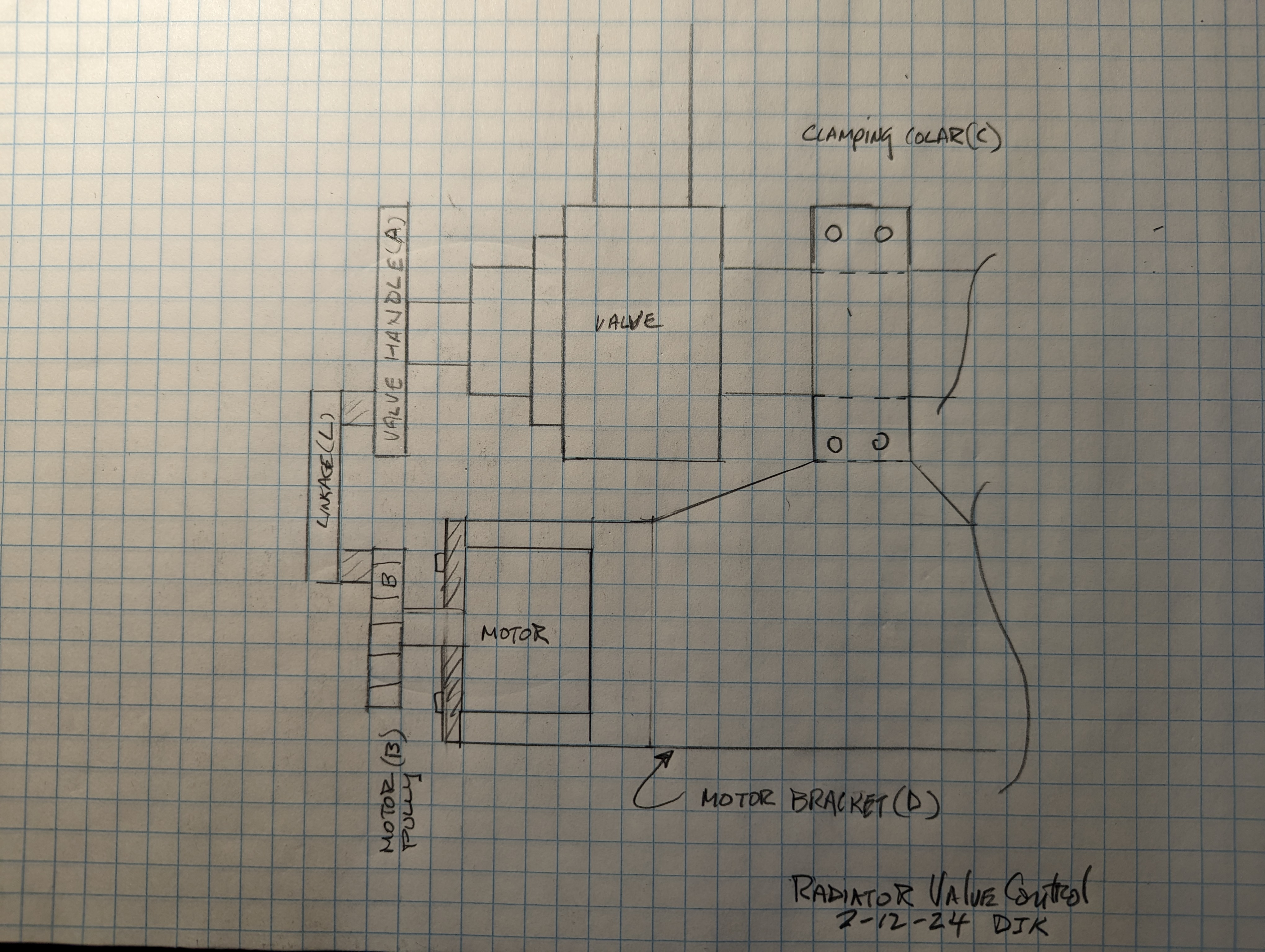
Hard to put ideas into words so here is a picture to help.
This is a top view only.
C: Clamping collar that is mounted to the pipe and has tapped holes to mount the motor bracket
D: The motor bracket mounts to the collar. Could be made to remove with thumbscrews. Motor and electronics mount on this bracket.
B: Pulley that connects the motor to the valve handle
C: Pulley that replaces the valve handle and connects the valve to the motor.
Drive options:
C&B are gears. Harder to make/procure, moderate ability to make pluggable
C&B are connected via a cog belt. Easier to make/procure, less ability to make pluggable
C&B are connected via linkage (L). Easy to make/procure, easy to make pluggable
You could, but that would not provide an option to make the unit plugable. It also looks like space in that direction is at a premium. Lastly, you still need some way to mount the motor to keep it from rotating.
Depending on the part you may be able to procure some of these parts, like cog gears and clamping collars. Best to decide on a design approach and then research each part’s procurement or fabrication. If you’re not using CAD this would be a good time to start . Once you have a design approach you can come back here for advice on fabrication.
If that is working it’s a good way to eliminate encoders or switches. What chip are you using?